Haltech E6K User Manual
Page 144
138
The S4 Hall Effect Sensor
The S4 sensor which is identified by a grey cable gland operates in the following way:
As a south pole passes the sensor face the signal in the secondary (PIN D) channel is
switched to a low state. As a north pole passes the sensor a low state will only occur on the
primary channel (PIN C).
The set-up for this sensor is similar to the S3 except that one extra magnet is required as well
as the orientation being changed. The north pole of the magnet is used to generate the main
trigger while a south pole is used to generate the home or synchronisation pulse.
Typical set-ups – S4
4 cylinder / 2 rotor engine
For a four cylinder 3 magnets are required in total. Two north poles positioned exactly 180
°
apart while a south pole needs to trigger the sensor before the trigger for cylinder No 1. The
positioning of the magnet for cylinder one is done the same way as the for the S3 making sure
the north pole is triggering the sensor at approximately 75
°
BTDC.
FIGURE 4: TYPICAL 4 CYLINDER/ 2 ROTOR APPLICATION
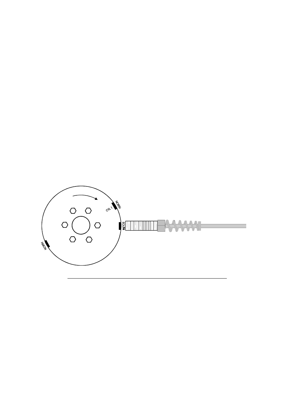
6 CYLINDER / 3 ROTOR ENGINE
For a six cylinder 4 magnets are required in total. The three north poles are positioned exactly
120
°
apart while a south pole need to trigger the sensor before the trigger for cylinder No 1.