Great Planes Spirit of St. Louis ARF - GPMA1151 User Manual
Page 13
❏ ❏
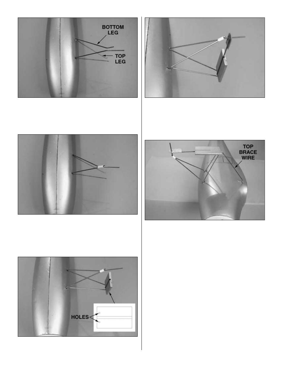
4. Next, insert the rear wire. There is a left and right
rear wire so make sure you are using the correct wire. The
longer end should be oriented as shown in the photo above.
❏ ❏
5. From the large white plastic tube cut two pieces 3/8”
[9.5mm] long. Use one to hold the bottom of the wires together.
Note: You may need to “tweak” the wires a bit to get them to
fit properly.
❏ ❏
6. Insert the ends of the top of the wires into the two
holes in the shock absorber assembly you made earlier.
❏ ❏
7. Insert the bottom brace wire assembly you made
earlier into the tube in the shock absorber assembly, then
insert the main landing gear wire into the hole in the wire
assembly as shown in the above photo.
❏ ❏
8. Insert the top brace wire into the tube in the top of
the shock absorber assembly and the top hole in the
fuselage. You may need to “tweak” the bends in the wires to
get the assembled landing gear system to fit properly.
❏ ❏
9. Time to glue the landing wires into the fuselage.
Remove the top brace wire and then carefully remove the
remainder of the landing gear assembly as a unit. Mix some
6-minute epoxy and put some into the three holes in the
fuselage. Insert the landing gear assembly and the top
brace wire back into the fuselage holes. After the epoxy has
hardened, mix a small amount of epoxy and fill the holes in
the fuselage. Be careful not to use an excessive amount of
epoxy as it could run inside the fuselage and add excess
weight to the model.
❏
10. Return to step 1 and install the landing gear to the left
side of the fuselage.
13