Assemble the landing gear – Great Planes Spirit of St. Louis ARF - GPMA1151 User Manual
Page 12
❏
3. Use a piece of cellophane tape on both sides of the
rudder to hold it to the rear of the fuselage.
❏
4. Temporarily connect the speed control and servos to
the receiver. Turn on the transmitter, then center the trims.
Connect the charged battery to the speed control. If the
servo arms are not centered, remove the arms from the
servos and center the arms.
❏
5. Cut two 1/8” [3mm] long pieces from the small white
plastic tube. Place one piece on the end of both pushrods
to hold them onto the servo arms. Place a small drop of CA
on each piece to hold it in place.
❏
6. With the pushrods connected to the servos and the
control surfaces, position the servo trays so the elevator and
rudder are neutral. Carefully glue the servo mounts to the
servo tray with medium CA.
❏
7. Now that the servos have been positioned and the
controls are centered, use 6-minute epoxy to glue the ends
of the pushrod guide tubes to the slots in the fuselage and
the slots in the pushrod brace. Be careful not to get any
epoxy into the ends of the pushrods.
❏
8. Mount the plywood tail braces (11, 12) to the bottom
of the stab and the fuse. Cut small slots in the bottom of the
fuse at the indentations to accommodate the ends of the
struts, but do not cut slots in the stab. Bevel ends at
stabilizer for a better fit and more gluing surface. Glue the
struts into position with epoxy.
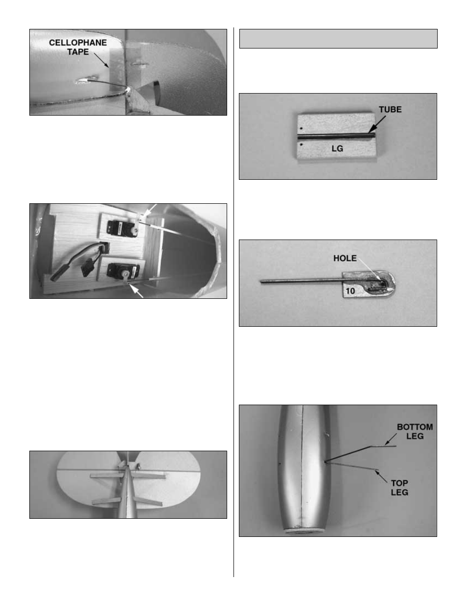
The landing gear looks delicate and difficult to install, but
they are actually very strong and quite easy to assemble.
We will start with the right landing gear assembly.
❏ ❏
1. Cut a piece from the small dark tube to the length of
the groove in the 1/8” [3.2mm] balsa part LG. Using epoxy,
glue the tube into the groove in LG. Drill two 1/16” [1.6mm]
holes where shown in the photo. This assembly will now be
referred to as the “shock absorber assembly”.
❏ ❏
2. Glue the 1/16” [1.6mm] wire landing gear part
shown in the photo to the 1/32” [0.8mm] ply part 10 with
6-minute epoxy. Be sure to align the wire part with the hole
marked on the ply part. When the epoxy has hardened,
enlarge the hole with a 1/16” [1.6mm] drill. This assembly
will now be referred to as the “bottom brace wire assembly”.
❏ ❏
3. Without using any glue, insert the forward landing
gear wire into the front slot in the fuselage. Both forward
landing gear wires are the same. The photo shows the
bottom of the fuselage viewed from the firewall.
Assemble the Landing Gear
12