Hook up the controls – Great Planes Spirit of St. Louis ARF - GPMA1151 User Manual
Page 11
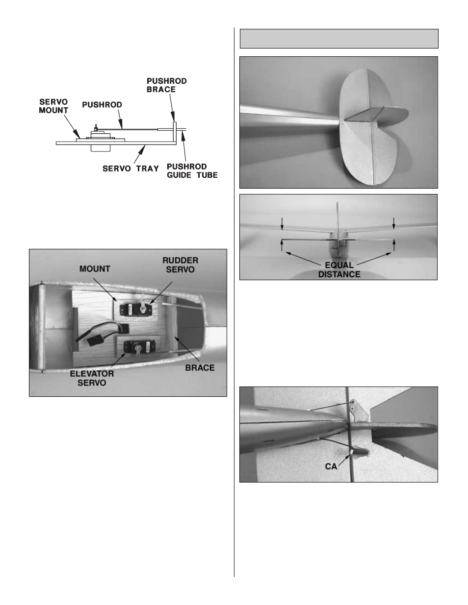
Refer to this sketch and the photograph for the
following two steps.
❏
4. Fit the servos into the 1/8” balsa servo mounts (I). Drill
1/16” holes through the servo mounts, then mount the
servos to the servo mounts with the screws that came with
the servos.
❏
5. Fit the servo mounts with the servos into the servo tray.
Do not glue the servo mounts to the servo tray until
instructed to do so. Connect the pushrods to the servos by
inserting them into the servo arm from the bottom. The
pushrods will be secured to the servo arm later. If the
pushrods do not align with the servos, cut slots in the
pushrod brace that will allow the pushrods to align as shown
in the photo and in the sketch. Use a long servo arm for the
rudder servo and a short arm for the elevator servo.
❏
1. Glue the stab and fin to the fuselage with 6-minute
epoxy. Make sure the fin is centered on the molded-in seam
on the top of the fuselage and that it is parallel with the
centerline of the fuselage. Before the epoxy hardens,
position the wing on the fuselage and view the wing and
stab from behind. If necessary, raise or lower one side of the
stab until it is parallel with the wing. Use pins to hold the
stab into position until the epoxy has fully hardened. Fill any
gaps between the fuse and the bottom of the stab sparingly
with additional epoxy.
❏
2. Connect the aft end of the pushrods to the control
horns on the elevator and rudder by inserting them into the
outermost hole. If necessary, make small bends in the
pushrods to get them to align with the holes in the horns. Be
certain there is a small amount of sideways tension in the
rods so they remain connected to the horns. Cut two 1/8”
[3mm] long pieces from the small white plastic tube. Place
one piece on the end of both pushrods to hold them onto
the control horns. Place a small drop of CA on each piece
to hold it in place.
Hook Up the Controls
11