Great Planes Reactor 3D EP ARF - GPMA1540 User Manual
Page 15
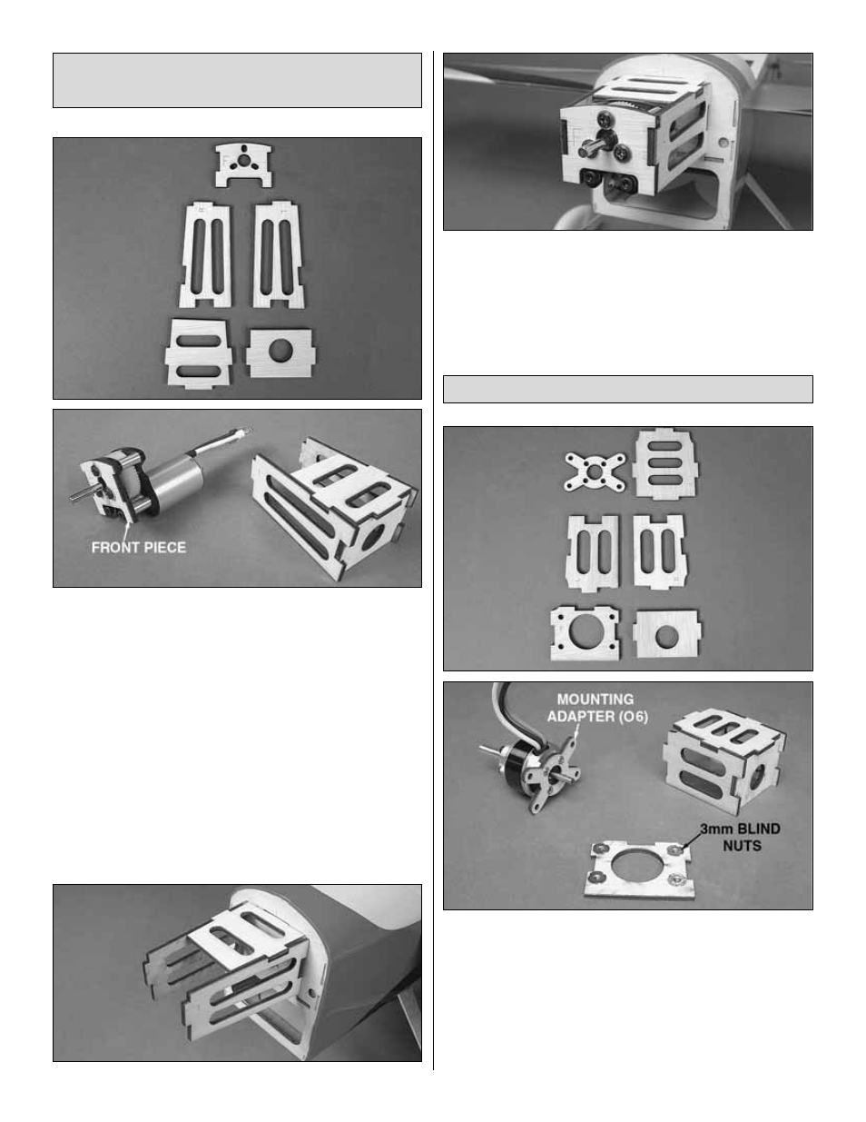
❏
1. Locate the five pieces that make up the in-runner motor
mounting box. These parts are labeled I1, I2, etc. Use medium
CA to glue the sides, top, and back pieces together. The “R,”
“L,” “T,” “B,” and “F” refer to right side, left side, top, back, and
front. Be sure that these letters appear on the outside of the
mounting box when assembled. Attach the front piece to the
motor gearbox using three 3 x 6mm machine screws (included
with the gearbox) and three 3mm washers.
❏
2. Glue the tabs on the back of the mounting box into the
slots in the firewall, being sure that the mounting box back
piece is flush against the firewall. Fit the motor leads through
the hole in the firewall and glue the front plate to the
mounting box with CA.
❏
1. Locate the six pieces that make up the out-runner motor
mounting box. These parts are labeled O1, O2, etc. Use
medium CA to glue the sides, top, and back pieces together.
The “R,” “L,” “T,” “B,” and “F” refer to right side, left side, top,
back, and front. Be sure that these letters appear on the
outside of the mounting box when assembled. Install four 3mm
blind nuts into the mounting holes in the front plate. Secure the
mounting adapter (O6) to the backside of your out-runner
motor using the screws supplied with the motor.
Out-runner Brushless Motor
In-runner Brushless Motor with
24mm Gear-Drive
15