Great Planes Reactor 3D EP ARF - GPMA1540 User Manual
Page 13
❏
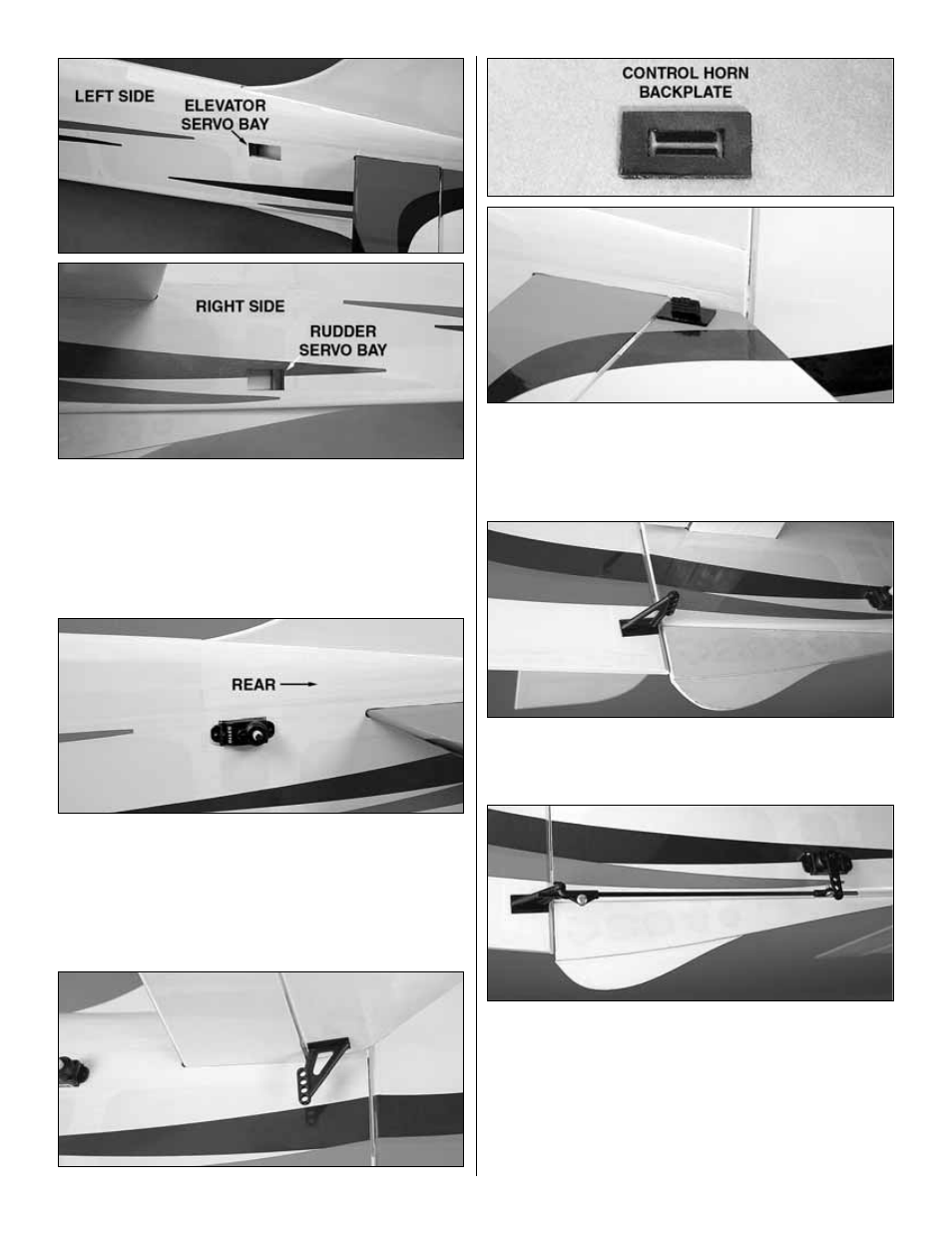
15. Trim the covering from the elevator and rudder servo
bays in the fuselage. The servo bay at the top left of the
fuselage is for the elevator. The bottom right servo bay is for
the rudder.
❏
16. Attach a 20" [500mm] servo extension to the rudder
and elevator servos. Feed the servo extensions through the
servo bays and down through the formers of the fuselage to
the cockpit area. Glue the servos into the servo bays with
the servo splines toward the rear of the plane.
❏
17. Insert a control horn into the slot on the underside of the
left elevator. Press a control horn backplate onto the control
horn tab on top of the elevator. Apply a few drops of CA glue
to the control horn and backplate to secure them in place.
❏
18. Attach a control horn to the right side of the rudder in
the same manner.
❏
19. Locate two double-sided servo arms to fit your rudder
and elevator servo splines. Cut one side from each double-
sided servo arm using the same method you did with the
aileron servos. With the arms both pointing down, make
pushrods using the two 6" [152mm] pushrods, four adjustable
clevises, and four 2 x 4mm self-tapping screws. Connect the
pushrods to the outer holes of the servo arms and control
horns. Adjust the elevator and rudder to the neutral position
and tighten the screws into the adjustable clevises.
13