Final assembly – Great Planes Dazzler 40 Kit - GPMA0480 User Manual
Page 12
12
❏
14 C. Test fit the cockpit floor to the top of the fuselage. It
may be necessary to slightly spread the two fuse sides at
the rear to allow a 1/16" edge from F3 to the location for the
canopy backrest. Glue the cockpit floor to the top of the
fuselage using medium CA.
❏
15. Cut and glue a 1/4" x 1/4" basswood hatch rail to fit
between the fuse sides in front of F2. Sand the top of the
rail to match the tapered angle of the fuse.
❏
16. Position a sheet of 3/32" x 4" wide balsa over the
fuel tank compartment with an edge butted against the top
sheeting at F2. The grain must run from front to rear. Trace
the outline on the bottom surface, then cut and sand the
hatch to fit. Drill four 1/16" pilot holes through the top of the
hatch into the hatch rail and firewall at the locations shown
for the #2 x 3/8" sheet metal screws.
❏
17. Test fit the canopy backrest former into position. Use
the Backrest Gauge to set the correct angle of the former.
After checking to make sure the former is aligned to both
sides of the cockpit floor, glue the backrest into position.
Glue the gauge into position to help support the former and
prevent it from getting accidentally knocked out of position.
FINAL ASSEMBLY
IMPORTANT: The wing is designed to fit snugly into the
fuse to provide a good glue joint between it and the fuse
sides. Work slowly and carefully when sliding the wing into
location to avoid damaging the cap strips or ribs. If too
much resistance is felt, remove the wing, then sand the
inside of the opening in the fuse to enlarge it slightly.
❏
1. With one wing tip on the floor, work the fuse down the
wing from the opposite end. Due to the close fit, the fuse
must be kept perpendicular to the wing or it will bind. You
will probably need to help each cap strip through the fuse
so take your time and work carefully.
❏
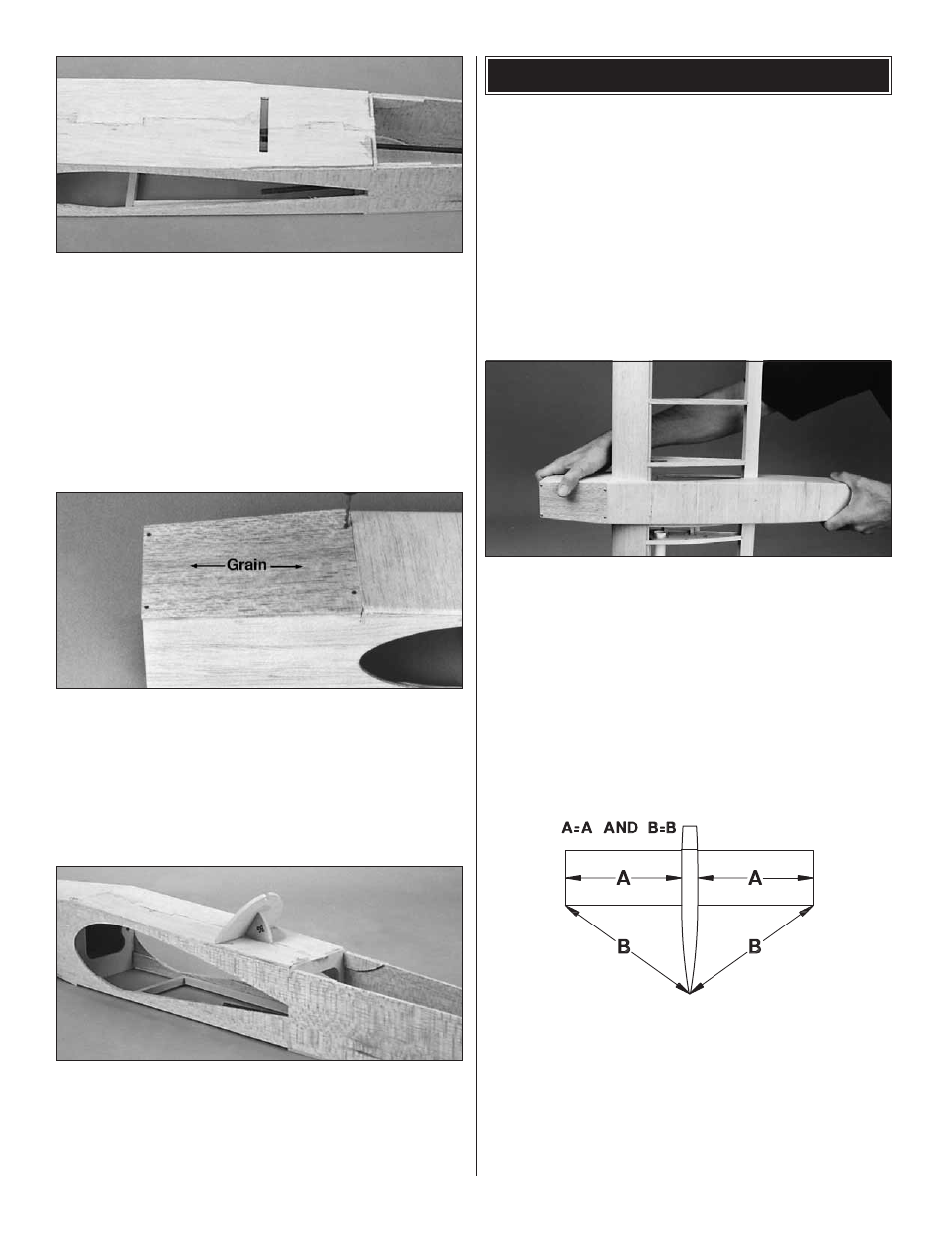
2. Once the wing is centered in the fuse, measure the
distance from each wing tip to the tail post. Shift the wing
until the measurements are equal. Mark the location of the
throttle pushrod through the F2 former onto the leading
edge of the wing. Slide the wing out of the fuse, far enough
to drill the location marked, using a 3/16" drill bit. Return
the wing to its previous location. When the wing alignment
is correct, use medium CA to securely glue the circumference
of the R1 ribs to the fuse. Fill any gaps with thick CA.