Great Planes Ultra Sport 60 Kit - GPMA0420 Pages 1-27 User Manual
Page 7
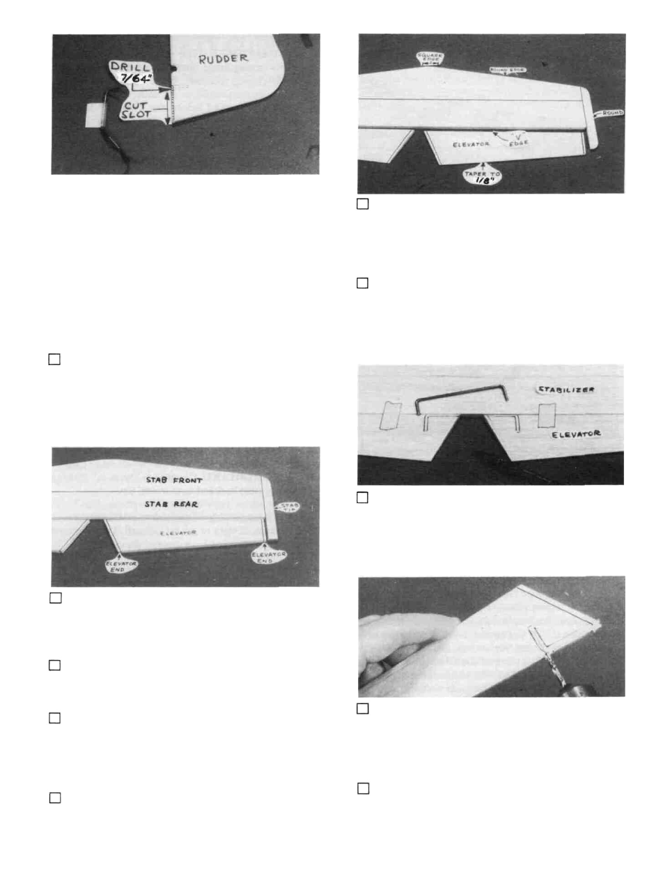
7/64" hole in the rudder, and groove the rudder leading edge
to accept the tailgear wire and the nylon tailgear bearing.
DO NOT GLUE YET! (The hole is drilled slightly oversize
to allow for positioning, and to create a hard epoxy "sleeve"
around the wire).
6. Sand both sides of the elevators to a taper as shown
on the plans. The trailing edge should end up approximately
1/8" wide and have a rounded shape (do not sand to a sharp
edge). Sand the leading edge to a "V-shape" as shown on the
plan.
7. Temporarily tape the elevators to the stab, providing
1/16" clearance between the elevator end and the stab tip.
BUILD THE STABILIZER AND
ELEVATORS
1. Find the following parts: 3/8" balsa stab front, stab
rear and elevators. You'll also need the 3/8" x 5/8" x 11"
balsa stab tip stock, the 1/8" elevator ends that you previ-
ously cut, and the 1/8" wire elevator joiner.
2. Glue the stab front to the stab rear. Then glue on
the stab tips. Sand the front of the stab tips to blend with the
stab.
3. Glue the elevator ends to the elevators and sand to
blend.
8. Lay the 1/8" wire elevator joiner in place on the
elevators and mark its outline using a fine point fell-tip pen.
4. Sand both sides of the stab smooth, then sand the
leading edge and lips to a rounded shape. (Leave the center
portion of the LE square). Draw a centerline along the
trailing edge of the stab to mark the hinge line.
9. Accurately drill holes in the elevators for the 1/8"
wire joiner. Begin by drilling a 1/16" or 5/64" pilot hole, then
drill the final hole to a depth of 7/8" with a 9/64" drill bit.
(The hole is drilled slightly oversize to allow for positioning,
and to create a hard epoxy "sleeve" around the wire).
tors.
5. Draw a centerline all around the edges of the eleva-
10. Using an Xacto knife, sharpen the inside of one end
of a 1/8" diameter brass tube and use it to cut grooves in the
7