Great Planes Ultra Sport 60 Kit - GPMA0420 Pages 1-27 User Manual
Page 19
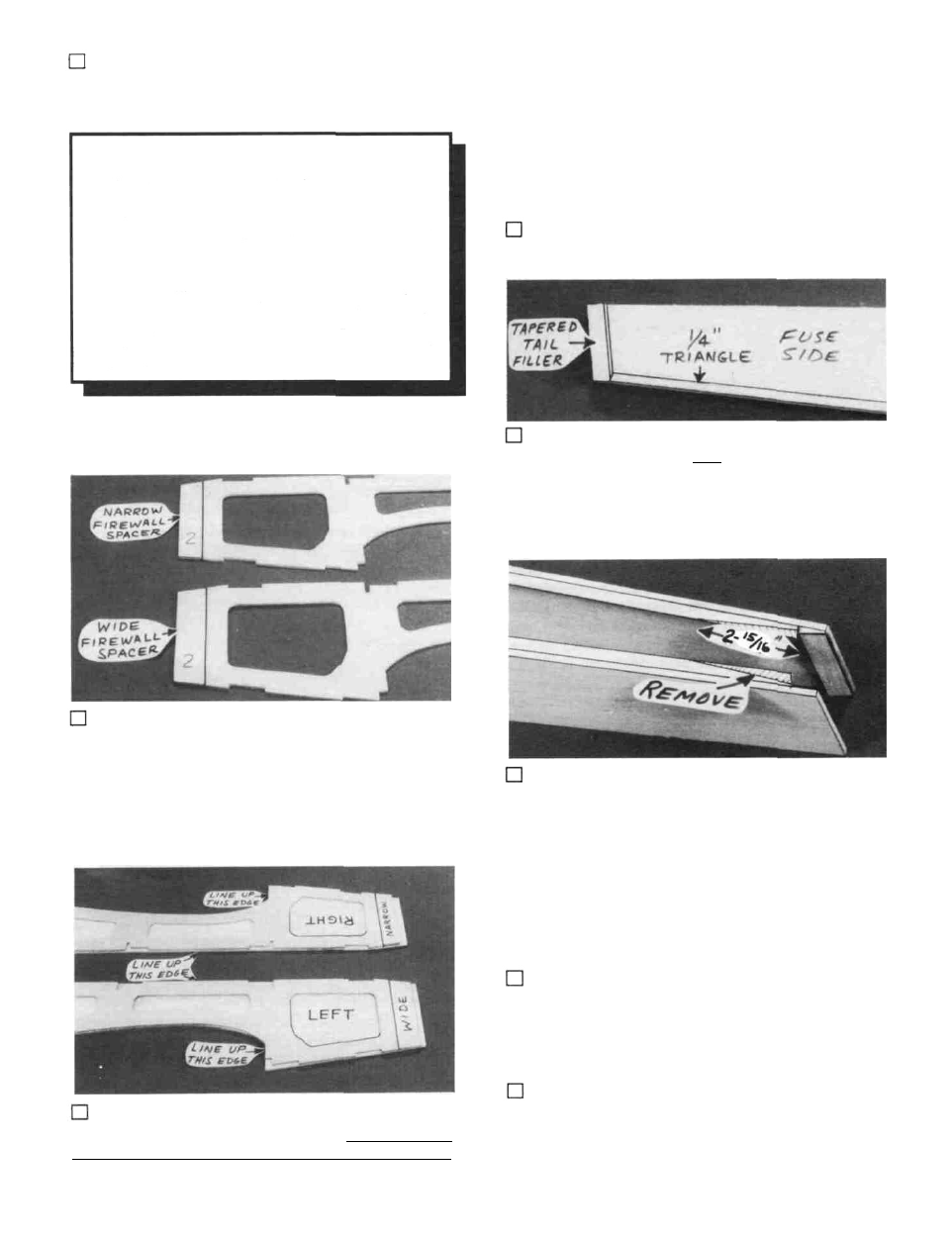
the four die-cut 1/8" ply firewall spacers. Note that the
spacers are marked "2 L", "2 R". "4 L", and "4 R".
Use the #2 firewall spacers if you will be install-
ing a 2-cycle engine such as the OS Max 61 SF.
Use the #4 firewall spacers if you will be install-
ing a small 4-cycle engine, such as the OS FS 70
Surpass.
If you will be installing a larger (longer) 4-cycle
engine, such as the OS FS 91 Surpass, do not use any
firewall spacer on the right side, and use the 1/8" x
1/8" x 3-5/8" hardwood stick as a firewall spacer on the
left side.
PLAN IT OUT! It is important that the fuse doubler and fuse
side line up along the top edge and the front of the wing
opening. While holding in position, apply thin CA glue
around all the notches and lightening holes, then around the
edges. Make sure you apply sufficient glue so it flows under
the doubler to produce a strong bond. NOTE: The narrow
and wide firewall spacers will automatically position the
firewall to result in 2-degrees of right engine thrust.
9. Glue the tapered balsa tail filler to the aft end of one
of the fuse sides and sand it even with the top and bottom
edges.
6. Find the two die-cut 1/8" ply fuselage doublers and
10. From the 1/4" balsa triangle, cut pieces to fit be-
7. Edge glue the appropriate firewall spacers to the
front edge of the fuselage doublers. Note that the spacers are
not the same size. They will automatically set the engine at
the required 2-degrees right thrust.
tween the tail filler and the rear of F-4, along the bottom
inside of both fuse sides. Glue in place.
11. Sand the aft ends of the balsa triangle to a taper,
which will permit the fuse sides to be pulled together at the aft
end. NOTE: The taper shown in the photo is approximate
and may have to be modified during assembly.
8. Carefully position the fuselage doublers on the fuse
sides, making a RIGHT and a LEFT side. The doubler with
the smaller firewall spacer goes on the right fuselage side ..
ASSEMBLE LOWER FUSELAGE
1. Tape the fuselage plan to your workbench and cover
the Fuse Bottom View with waxed paper.
NOTE: The fuselage is assembled upside down.
2. Pin or tack glue (using 3M "77" Spray Adhesive)
the 1/8" die-cut balsa stab base accurately in position on the
plan. Align the front edge of the stab base with the line on the
plan.
19