Great Planes Ultra Sport 60 Kit - GPMA0420 Pages 1-27 User Manual
Page 27
NOTE: The turtle deck is designed to be as light as possible,
while still providing sufficient durability for normal use. If
your airplane will be handled by "ham-fisted" people who
like to squeeze hard when holding the airplane in the turtle
deck area, you may want to add an extra 1/4" x 1/4" balsa
stringer on the inside of the turtle deck sheeting, between
F-3A and F-4A, about halfway down.
HINT: For a super-smooth and uniform finish on your turtle
deck, cut a 2-1/4" x 11" strip of 320 or 400-grit wet-or-dry
sandpaper, and work it like a "shoe-shine cloth" across the
top of the turtle deck.
ASSEMBLE THE NOSE SECTION
block to the tops of the formers, stringers and sheeting, then
trim the ends of the top block flush with F-3A and F-6A.
11. Glue the 1/2" x 2-3/8" x 26" balsa turtle deck top
HINT: In the next step it will be helpful in keeping the
top block symmetrical if you first mark a centerline on the
top of the top block from front to back (this is a line from the
centerline of F-3A to F-6A).
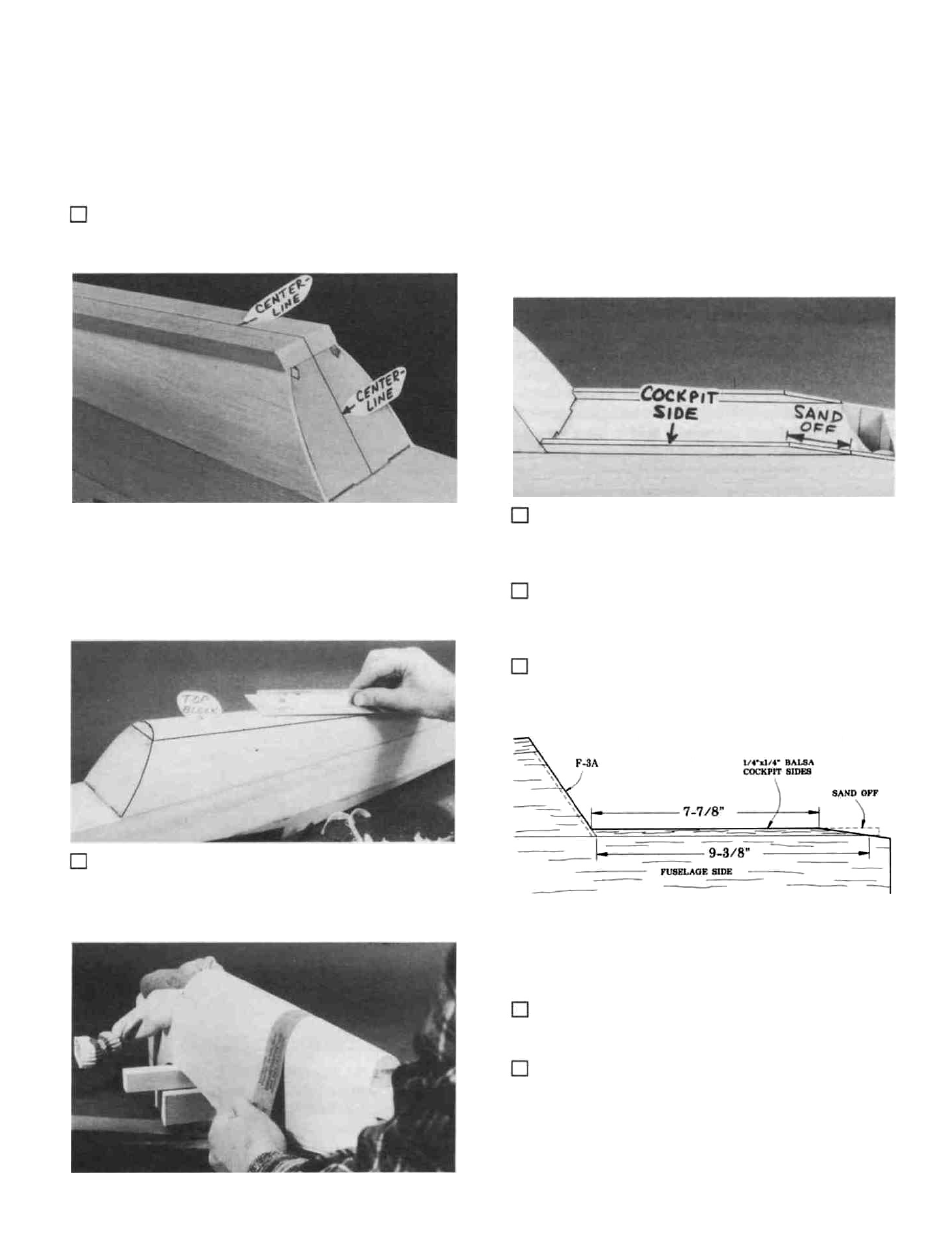
1. Find the 1/4" x 1/4" x 10" balsa cockpit sides. Cut
off one end of each stick at an angle to fit the front edge of the
backrest (F-3A).
2. Glue the cockpit sides to the top edge of the fuse
sides and to F-3A. The outside edge of the cockpit sides
should be flush with the outside edge of the fuse sides.
12. Carve and sand the top block to blend smoothly with
the sheeting (see the cross-sections on the plan). HINT: Use
a razor plane (or a sharp wood chisel) and a sanding block
with 50-grit sandpaper for rough shaping the top block.
3. Measure, mark and sand off the cockpit sides ac-
cording to the sketch. Then sand the top front comers of the
fuse sides on the same angle, to blend with the cockpit sides.
4. Attach the engine mount to F-l, and attach the
engine to the mount Remove the nose gear.
5. From a scrap of 1/32" ply, cut four small pieces and
tack glue them to the 1/16" ply spinner ring as shown, using
a very small amount of thick CA (these will be removed
later). IMPORTANT NOTE: If you have chosen to use
shock-absorbing rubber engine mounts, then you must pro-
vide more space between the spinner ring and the spinner
27