Great Planes Super Stearman 1.20 ARF - GPMA1350 User Manual
Page 18
❏ ❏
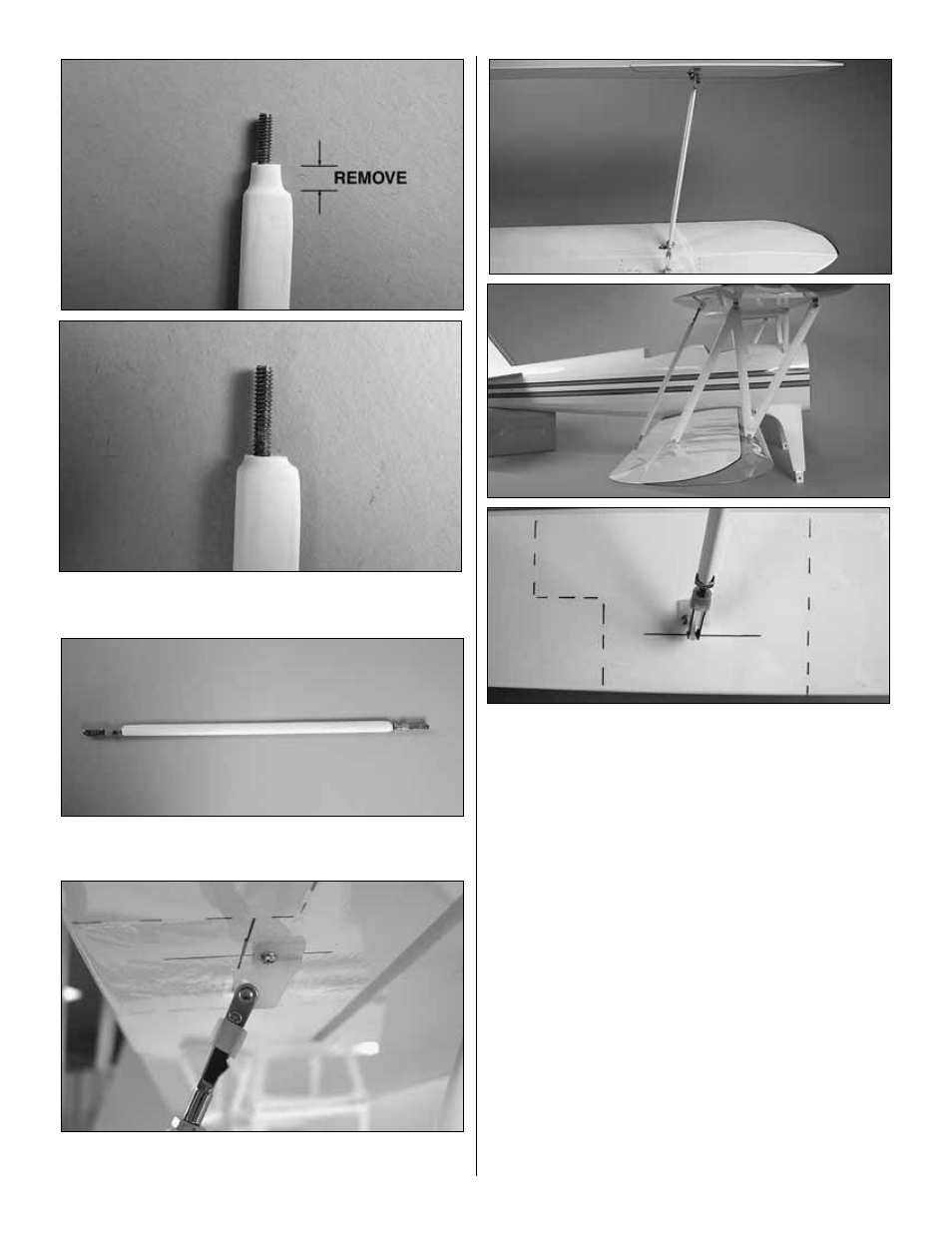
6. Locate the aileron connecting rod. Cut the excess
rubber coating to expose all of the threads.
❏ ❏
7. Install a 4-40 nut, 4-40 metal clevis and a silicone
clevis keeper on both ends of the connecting rod.
❏ ❏
8. Install one end of the connecting rod to the outer
hole of the control horn on the aileron of the top wing.
❏ ❏
9. Attach the remaining control horn to the other end of
the connecting rod. Adjust the clevises so that the length of
the connecting rod allows the top aileron and bottom
ailerons to be neutral.
Place the control horn on the aileron of the bottom wing.
position it as needed until the connecting rod is aligned with the
back of the “N” strut and parallel to the “N” strut as viewed from
the side. Once properly positioned, mark the location of the
clevis holes. This will make the center of the clevis holes
approximately 1" [25mm] from the trailing edge of the aileron.
❏ ❏
10. Drill a 1/16" [1.6mm] hole through each of the
marks. Be sure to drill only through the plywood plate. Insert
and remove a #2 x 3/8" [10mm] sheet metal screw into each
of the holes. Apply a couple of drops of thin CA into the
holes to harden the threads. After the glue cures mount the
control horn with the screws.
❏ ❏
11. Make any additional adjustments to the clevises on
the ends of the connecting rod as needed until both the top
and bottom aileron are neutral. Tighten the 4-40 nuts
against the clevises on the connecting rod to prevent the
connecting rod from rotating.
❏
12. Repeat steps 1-11 for the left wing.
18