Great Planes HyperFlow Ducted Fan System - GPMG3910/3911 User Manual
Page 7
7
❏
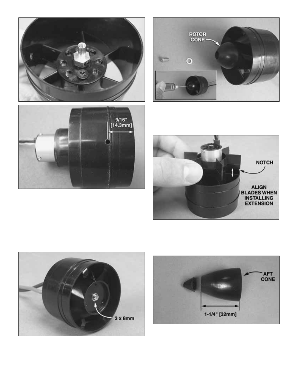
4. Press the fan rotor adapter onto the motor and tighten
the set screws against the shaft. Allow a small amount of
clearance (1/8" [3mm]) between the base of the adapter and
the motor to prevent binding. A 3/32" [2.4mm] hole can be
drilled into the side of the fan housing 9/16" [14.3mm] from
the front edge to insert an allen wrench for the fan adapter
set screws.
❏
5A. Fit the fan rotor over the brass fan adapter and push
it down so it is fully seated. If you will not be installing the
optional rotor cone, thread a 3 x 8mm Phillips screw with
a 3mm washer through the fan adapter. Be sure to use
threadlocking compound.
❏
5B. If you are installing the optional rotor cone, press it onto
the fan rotor as shown. Insert a 3 x 8mm Phillips screw and
3mm washer (with threadlocking compound) into the hole in the
rotor cone and tighten the screw into the brass fan adapter.
❏
6. Slide the stator extension onto the back of the ducted fan
housing. There are small notches on the stator extension that
fi t around the fan housing. Be sure that the extension blades
are aligned with the stator blades inside the motor housing.
Secure the extension with a couple drops of CA glue.
❏
7. Cut a portion of the aft cone away for motor cooling and
to allow the motor leads to pass through. For most motor
applications, the aft cone should be approximately 1-1/4"
[32mm] long after cutting it. If using a long brushless motor,
the aft cone may not fi t and can be omitted. If you are going to
run a high power set-up, you can omit the aft cone to improve
motor cooling.