9363-pendant-i, Installation instructions, Ac a – Golden Lighting 9363-M3 GMT-OP User Manual
Page 3
INSTALLATION INSTRUCTIONS
Fixture Name:
Presilla 9363-9, -5, -M1L, -M3 GMT
For Pendant Light Fixture
For Customer Service, contact the place of purchase to arrange for replacement parts.
WARNING ! SHUT OFF POWER AT FUSE OR CIRCUIT BREAKER.
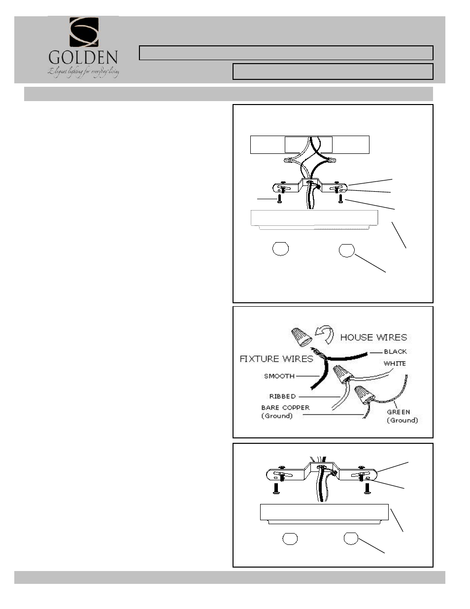
HANGING THE FIXTURE (Fig. 1)
1. Carefully remove the new fixture from the carton and
the yellow bag that holds all your parts. Check that all
parts are included as shown in the illustration and parts
list.
2. Shut off power at the circuit breaker and remove the
old fixture from ceiling, including the old mounting strap.
3. The Mounting Strap (B) contains several pairs of
threaded holes, find the pair of holes that match the hole
spacing in your fixture Canopy (G) and thread the two
Mounting Screws (C) into the Mounting Strap (B) facing
down, Secure in place with hex nuts. These will have their
threaded ends protrude through the two holes in the
fixture canopy (G).
4. Place the Mounting Strap (B) over the junction
5. Attach the Mounting Strap (B) to the Junction Box
using the two mounting screws (A). Tighten the screws
(B) securely with screw driver.
Fig. 1
CONNECTING THE WIRES (Fig. 2)
6. Attach the power supply wires to the fixture lead wires
by connecting BLACK to BLACK (or SMOOTH) and
WHITE to WHITE (or RIBBED).
7. Attach the GROUND wire(GREEN or COPPER) from
the Junction Box and the fixture Ground wire to the green
Ground Screw on the Mounting Bracket (B) or connect
both wires together using the correct size of wire
connectors.
NOTE: Twist the wires together in the same direction you
twist the wire connector onto the wires.
8. Tuck these wire connections neatly into the Junction
Box.
Fig. 2
FINISHING THE INSALLATION (Fig. 3)
9. Place the fixture’s canopy over the Mounting Strap (B)
and over the Mounting Screws (C), adjust the fixture
Canopy (G) until the Mounting Screws (C) protrude out
from the Canopy (G) and secure the fixture against the
ceiling by threading the Decorative nuts(F) until tight.
YOUR INSTALLATION IS NOW COMPLETE. RETURN
POWER TO THE JUNCTION BOX AND TEST THE
FIXTURE.
Fig. 3
JUNCTION
BOX
(CEILING)
A
C
A
C
B
G
F
G
F
B