Installation instructions, Mk l h j – Golden Lighting 5221-2 RBZ-TEA User Manual
Page 2
For Wall Mount Light Fixture
INSTALLATION INSTRUCTIONS
WARNING ! SHUT OFF POWER AT FUSE OR CIRCUIT BREAKER.
Fixture Name: Brookfield 5221-2 CH , ORB, PW and 5332 RBZ
For Customer Service, contact the place of purchase to arrange for replacement parts.
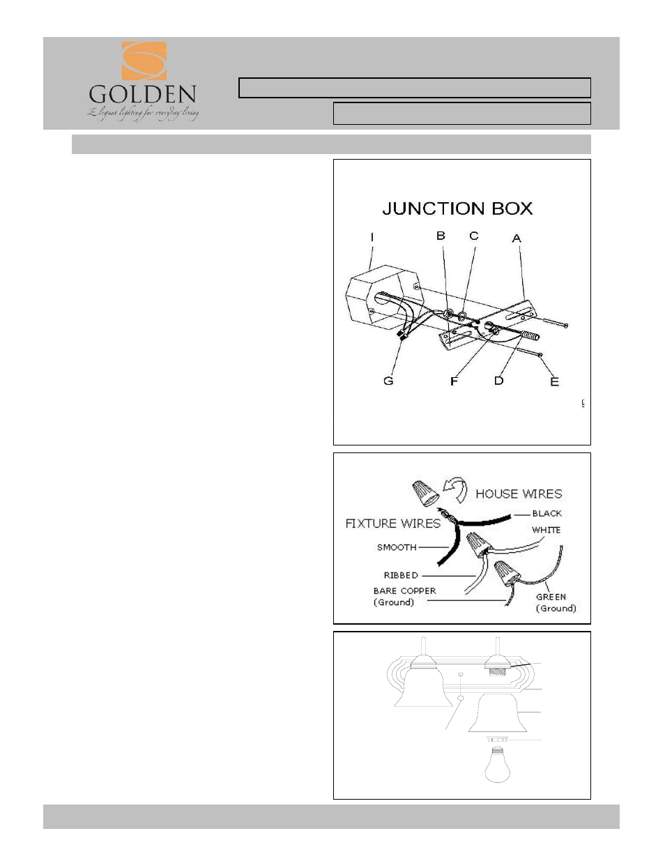
HANGING THE FIXTURE(Fig.1)
1. Carefully remove the new fixture from the carton and
the yellow bag that holes all your parts. Check that all
parts are included as shown in the illustration and parts
list.
2. Shut off power at the circuit breaker and remove the
old fixture from wall, including the old mounting strap.
3. Thread the Nipple (D) into the Mounting Strap (A).
Place Lock Washer (C) over end of Nipple (D)
protruding through Mounting Strap (A) and thread Hex
Nuts (B) onto Nipple until tight.
4. The Mounting Strap(A) contains several pairs of
threaded holes, find the pair of holes that match the
holes spacing in your fixture Back Plate(J) and thread
the two Mounting Screws(E) half way into the Mounting
Strap(A).
CONNECTING THE WIRES (Fig 2)
6. Attach the power supply wires to the fixture lead
wires by connecting BLACK to BLACK (or SMOOTH)
and WHITE to WHITE (or RIBBED).
7. Attach the GROUND wire(GREEN or COPPER)
from the Junction Box and the fixture Ground wire to
the green Ground Screw on the Mounting Bracket (A)
or connect both wires together using the correct size of
wire connectors. -
NOTE:Twist the wires together in the same direction
you twist the wire connector onto the wires.
8. Tuck these wire connections neatly into the Junction
Box.
FINISHING THE INSTALLATION(Fig.3)
9. Place the fixture Back Plate ( J ), over the threaded
rod, so it protrudes through the hole in the Back Plate
(J). Thread the Deco Nut ( H ) onto the threaded rod
and continue turning until the Back Plate(J) is snug
against the wall.
10. Install the light bulbs and glass shade as per the
fixture assembly sheet.
YOUR INSTALLATION IS NOW COMPLETE.
RETURN POWER TO THE JUNCTION BOX AND
TEST THE FIXTURE.
Fig. 1
5. Place the Mounting Strap(A)over the Junction Box
so the Mounting Screws(E) are vertical or horizontal, as
required by fixture type and fasten using the two
mounting screws (B). Tighten the screws (B) securely
with screw driver.
Fig. 3
Fig. 2
M
K
L
H
J