Installation instruction ch-2, For multi tier light fixtures, Suggested installation (fig.1) – Golden Lighting 2501-20 NWB User Manual
Page 2: Connecting the wires (fig.2), Warning! shut power off at fuse or circuit breaker
INSTALLATION INSTRUCTION CH-2
For Multi tier Light fixtures
IMPORTANT: FOR A SAFE AND SECURE INSTALLATION, THESE FIXTURES MUST BE
INSTALLED BY MEANS OF SUPPORTS THAT ARE INDEPENDENT OF THE OUTLET BOX.
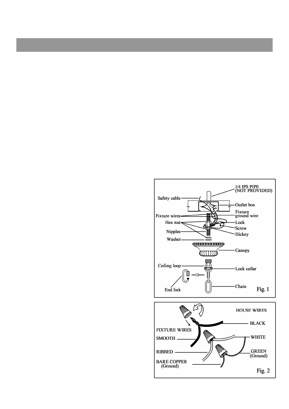
SUGGESTED INSTALLATION (Fig.1)
1. Provide a 1/4 IPS pipe with one end securely
mounted to a beam or a structural member. The
other end should protrude through the center of
the outlet box as shown.
2. Assemble the ceiling loop, nipple, nuts & hickey
to center 1/4 IPS support pipe and adjust overall
length to allow the lock collar to hold the canopy
flush to the ceiling.
3. Attach the chain to the fixture loop by opening
the end link.
4. Slip the lock collar (finish side down) & canopy
over the upper end of the chain. Open the upper
end link of chain, now lift the fixture and hang it
on the Ceiling loop tighten both end links.
5. Lace the fixture wires, ground & safety cable
through the chain & loop, exiting through the
side of the hickey. Place the safety cable through
the lock, now wrap it twice around the hickey &
run the end back through the lock, tighten the set
screw on the side of the lock. Run cable through
the top of the outlet box and secure to structural
member.
6. Install the light bulbs & glass. (See glass
installation instruction enclosed.)
CONNECTING THE WIRES (Fig.2)
7. Place the white, ribbed, or tinned wire from the
fixture evenly against the white wire from the
Outlet Box.
8. Fit the connector over the ends of the two wires
and screw the connector clockwise until you feel
a firmness.
9. Try gently to pull the connector off the wires. If
you can pull the connector off, carefully redo
steps 6 and 7 above, and check again for a firm
connection.
10. Connect the black, smooth, or untinned wire
from the fixture to the black wire from the Outlet
Box in the same manner.
11. If your Outlet Box is provided with a ground
wire (green or bare copper only), attach this wire
and the bare copper wire from the fixture to the
ground screw by wrapping both wires under the
head of the screw and tightening screw. If Outlet
Box is not provided with ground wire, attach
only the bare copper wire from the fixture to the
ground screw.
WARNING: DO NOT ATTACH ANY
OTHER WIRES BESIDES THE GREEN OR
BARE COPPER WIRE TO THE GROUND
SCREW.
12. After the wires are connected, tuck them
carefully inside the outlet box. Then raise the
Canopy up against the ceiling & screw the Lock
Collar onto the Ceiling Loop.
NOTE: DO NOT EXCEED THE SPECIFIED
WATTAGE.
Your installation is now complete. Turn power on
at to the junction box & test the fixture.
CSKLG005
WARNING! SHUT POWER OFF AT FUSE OR CIRCUIT BREAKER