2073-4 gmt installation instructions part 1, Installation instructions, Warning! shut power off at fuse or circuit breaker – Golden Lighting 2073-4 WG User Manual
Page 2
F
For Customer Service, contact the place of purchase to arrange for replacement parts.
2073-4 GMT INSTALLATION INSTRUCTIONS PART 1
INSTALLATION INSTRUCTIONS
Fixture Name: SMYTH 2073-4 GMT
For Chandelier Light Fixture
WARNING! SHUT POWER OFF AT FUSE OR CIRCUIT BREAKER
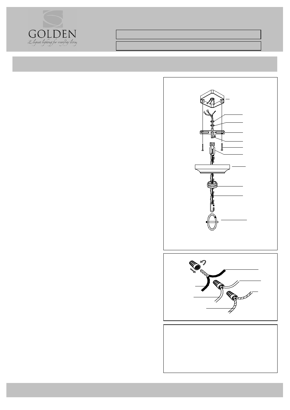
HANGING THE FIXTURE (Fig.1)
1. Carefully remove the new fixture from the carton and the
yellow bag that holds all parts. Check that all parts are
included as shown in the illustration and the Parts List.
2. Shut off the power at the circuit breaker and remove the
old fixture from the ceiling, including the old mounting
strap.
3. Thread Nipple (C) into Canopy Loop (F) until snug.
4. Thread the other end of Nipple (C) with Canopy Loop (F)
attached into Mounting Strap (D).
5. Place Lock Washer (B) over the end of Nipple (C) which
should protrude through Mounting Strap (D). Thread Hex
Nuts (A) onto Nipple (C) until tight.
6. Take this mounting strap assembly and mount to ceiling
junction box using Junction Box Screws (E). Tighten the
screws securely with screw driver.
7. Unscrew the Canopy Loop Collar (H) from Canopy Loop
(F). Take the Canopy (G) and pass over the Canopy Loop
(F). Approximately one half of the Canopy Loop (F) exterior
threads should be exposed. Adjust until desired height is
reached, The Canopy Loop Collar (H) should fit snugly on
Canopy Loop (F) after the canopy is installed. Remove
Canopy (G) and Canopy Loop Collar (H)
8. Assemble the fixture and have an assistant or secure a
support to hold the weight of the fixture while you complete
the wiring connections.
9. Thread the fixture wires and ground wires of the assembled
fixture through the chain loops, Canopy Loop (F), Nipple
(C) and into the Junction Box.
CONNECTING THE WIRES (Fig.2)
10. Attach the power supply wires to the fixture lead wires by
connecting BLACK to BLACK (or SMOOTH) and WHITE to
WHITE (or RIBBED) .
11.
Ground wire connection: Connect the fixture
ground wire to the supply ground wire (this usually has
green insulation) with wire connector. If there is no
supply ground wire at ceiling junction box then attach
the fixture ground wire securely onto the green
grounding screw located at mounting bar.
NOTE: Twist the wires together in the same direction you
twisted the wire connector onto the wires.
12. Tuck these wire connections neatly into the Junction Box.
13. Raise Canopy (G) to the ceiling and secure in place by
tightening the Canopy Loop Collar (H) into the Canopy
Loop (F).
14. Install the light bulbs and glass shade as per the Parts and
Assembly Sheet.
Fig. 1
Fig.2
YOUR INSTALLATION IS NOW COMPLETE.
RETURN POWER TO THE JUNCTION BOX
AND TEST THE FIXTURE
FIXTURE
WIRES
SMOOTH
(Or Black)
RIBBED
(
i )
HOUSE
WIRES
BLACK
(Hot)
WHITE
G
CHAIN
J
H
F
E
D
JUNCTION BOX
(CEILING)
A
C
B