19 table 10 — quick access chart – Carrier AQUAZONE 50RLP User Manual
Page 19
19
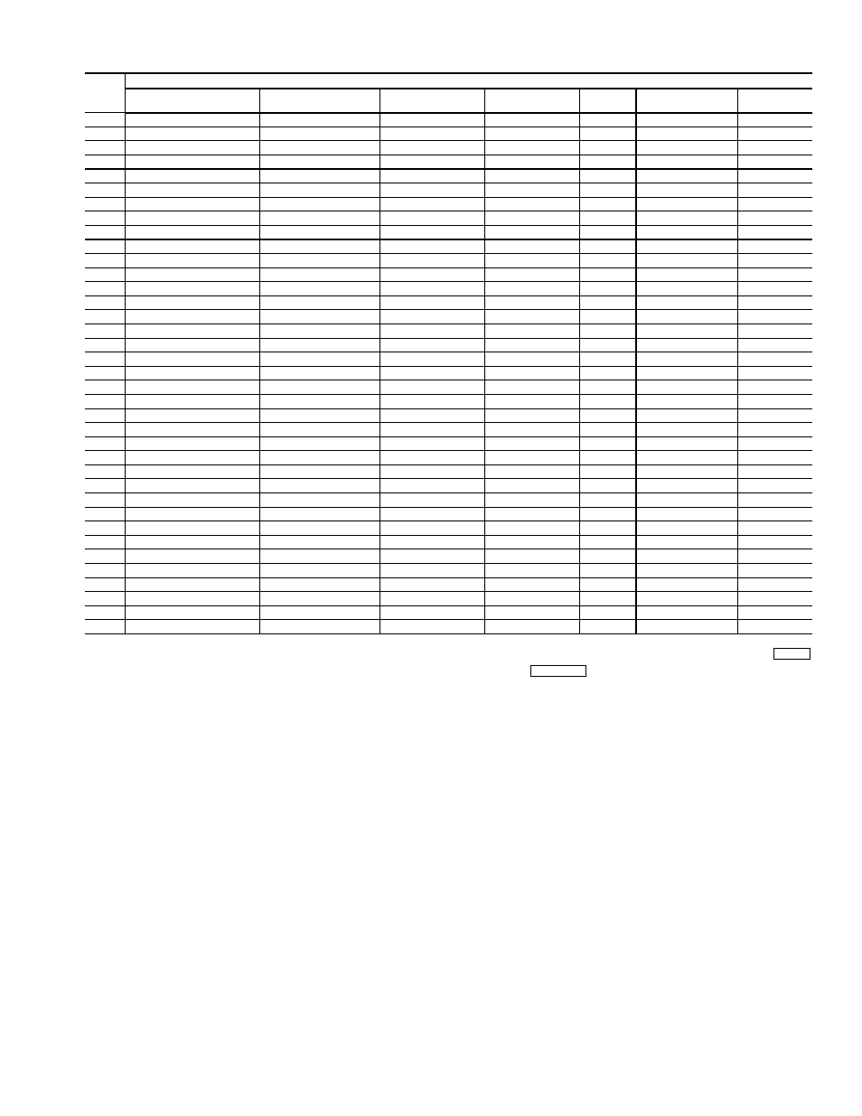
Table 10 — Quick Access Chart
LEGEND
NOTES:
1. If in the Edit mode and wish to switch to the Status mode, press
or press
again.
2. Not all available selections will have items to select in sublevels.
LID
NUM.
KEY
LID FUNCTION KEYS
Algorithms
(ALGO)
Status
(STAT)
History
(HIST)
Service
(SRVC)
Alarm
(ALRM)
Setup
(SET)
Schedules
(SCHD)
1
AO—Adaptive Control
Hardware Points
Alarm History
Function Definition
Limit
Set Clock
Occupancy
2
AO—Cooling CV
Software Points
Analog Point Trace
Channel Definition
Setpoint
Real Time Clock
Setpoint
3
AO—Cooling VAV
Temperature Input
Discrete Point Trace
System Definition
Discrete
Controller Password
Holiday
4
AO—Fan Tracking
Milliamp Input
Consumable Channel
Setpoint Definition
First out
N/A
S/W Setpoint
5
AO—Heating CV
Custom Milliamp Input
Internal Consumable
Database Control
Runtime
N/A
Network Time
6
AO—Heating VAV
Voltage Input
Runtime Channel
Comfort Controller
# of starts
N/A
N/A
7
AO—Humidity Control
Custom Voltage Input
N/A
CCN Control
N/A
N/A
N/A
8
AO—Mixed Air CV w/IAQ
Sensed Discrete Input
N/A
LID Preferences
N/A
N/A
N/A
9
AO—Mixed Air VAV w/IAQ
Latched Discrete Input
N/A
N/A
N/A
N/A
N/A
10
AO—Permissive Interlock
Pulsed Discrete Input
N/A
N/A
N/A
N/A
N/A
11
AO—Reset
Milliamp Output
N/A
N/A
N/A
N/A
N/A
12
AO—Shared Transducer
Custom Milliamp Output
N/A
N/A
N/A
N/A
N/A
13
AO—Static Pressure
Voltage Output
N/A
N/A
N/A
N/A
N/A
14
DO—Analog
Custom Voltage Output
N/A
N/A
N/A
N/A
N/A
15
DO—DX-Staging VAV
Discrete Output
N/A
N/A
N/A
N/A
N/A
16
DO—Electric Heat CV
Stepper Motor Output
N/A
N/A
N/A
N/A
N/A
17
DO—Electric Heat VAV
Discrete Software Point
N/A
N/A
N/A
N/A
N/A
18
DO—Enthalpy Comparison
Analog Software Point
N/A
N/A
N/A
N/A
N/A
19
DO—Interlock
Network Data Out
N/A
N/A
N/A
N/A
N/A
20
DO—Lighting Control
Network Data In
N/A
N/A
N/A
N/A
N/A
21
DO—Permissive Interlock
N/A
N/A
N/A
N/A
N/A
N/A
22
DO—Pump Control
N/A
N/A
N/A
N/A
N/A
N/A
23
DO—Prop Thermo
N/A
N/A
N/A
N/A
N/A
N/A
24
DO—Prop Thermo 2 Pipe
N/A
N/A
N/A
N/A
N/A
N/A
25
DO—Prop Thermo 4 Pipe
N/A
N/A
N/A
N/A
N/A
N/A
26
DO—Staged Thermostat
N/A
N/A
N/A
N/A
N/A
N/A
27
DO—Staging Control
N/A
N/A
N/A
N/A
N/A
N/A
28
DO—Time Clock
N/A
N/A
N/A
N/A
N/A
N/A
29
DO—Time Clock w/Check
N/A
N/A
N/A
N/A
N/A
N/A
30
AOSS Schedule
N/A
N/A
N/A
N/A
N/A
N/A
31
Network Broadcast
N/A
N/A
N/A
N/A
N/A
N/A
32
Linkage/AOSS Schedule
N/A
N/A
N/A
N/A
N/A
N/A
33
NTFC w/Enthalpy Check
N/A
N/A
N/A
N/A
N/A
N/A
34
Sensor Group
N/A
N/A
N/A
N/A
N/A
N/A
35
WSM Air Source
N/A
N/A
N/A
N/A
N/A
N/A
36
WSM Cool Source
N/A
N/A
N/A
N/A
N/A
N/A
37
Custom Program
N/A
N/A
N/A
N/A
N/A
N/A
AO
— Analog Output
AOSS — Adaptive Optimal Start/Stop
CV
— Constant Volume
DO
— Digital Output
IAQ
— Indoor Air Quality
N/A
— Not Available
NTFC
— Nighttime Free Cooling
VAV
— Variable Air Volume
WSM
— Water System Manager
CLEAR
EXPN/EDIT