Check the control throws, Balance the model (c.g.) – Flyzone FLZA3300 User Manual
Page 13
13
If the ESC does not operate properly or makes a
low pitched beeping sound following the above set-
up procedure, disconnect the battery from the ESC,
reverse the throttle setting on the transmitter and repeat
the ESC set-up.
SAFE-START:
As a safety precaution to prevent the motor
from rotating when the battery is fi rst connected, you must
“arm” the ESC every time you connect the battery. The
propeller will NOT rotate until the ESC is armed. To arm the
ESC, move the throttle stick to full position, then back to “off”
(or “brake”).
Now the motor will rotate anytime the throttle
stick is advanced away from the “off” position! Care
must be exercised when near the model’s propeller!
Check the Control Throws
The Switch Trainer EP RTF is setup from the factory
with the recommended control throws for the high wing
confi guration. If at any time you wish to return to the
default control throws, or if you simply want to confi rm the
throws, use the following measurements:
NOTE
: The throws are measured at the
widest part
of the
elevators, rudder and ailerons.
These are the recommended control surface throws:
ELEVATOR
Up & Down
1/2"
[13 mm]
16 deg
RUDDER
Right & Left
3/4"
[19 mm]
12 deg
AILERONS
Up & Down
1/4"
[6 mm]
9 deg
ELEVATOR
Up & Down
5/8"
[16 mm]
20 deg
RUDDER
Right & Left
1"
[25 mm]
17 deg
AILERONS
Up & Down
HIGH
WING
CONFIGURA
TION
LO
W
WING
CONFIGURA
TION
5/16"
[8 mm]
11 deg
Balance the Model (C.G.)
More than any other factor, the C.G. (center of gravity/
balance point) can have the greatest effect on how a
model fl ies and could determine whether or not your fi rst
fl ight will be successful. If you value your model and wish
to enjoy it for many fl ights,
DO NOT OVERLOOK THIS
IMPORTANT PROCEDURE.
A model that is not properly
balanced may be unstable and possibly unfl yable.
At this stage the model should be in ready-to-fly condition
with
all
of the components in place including the complete
radio system, battery, canopy hatch, etc. The following
procedure is the same for both the high wing and low
wing configurations.
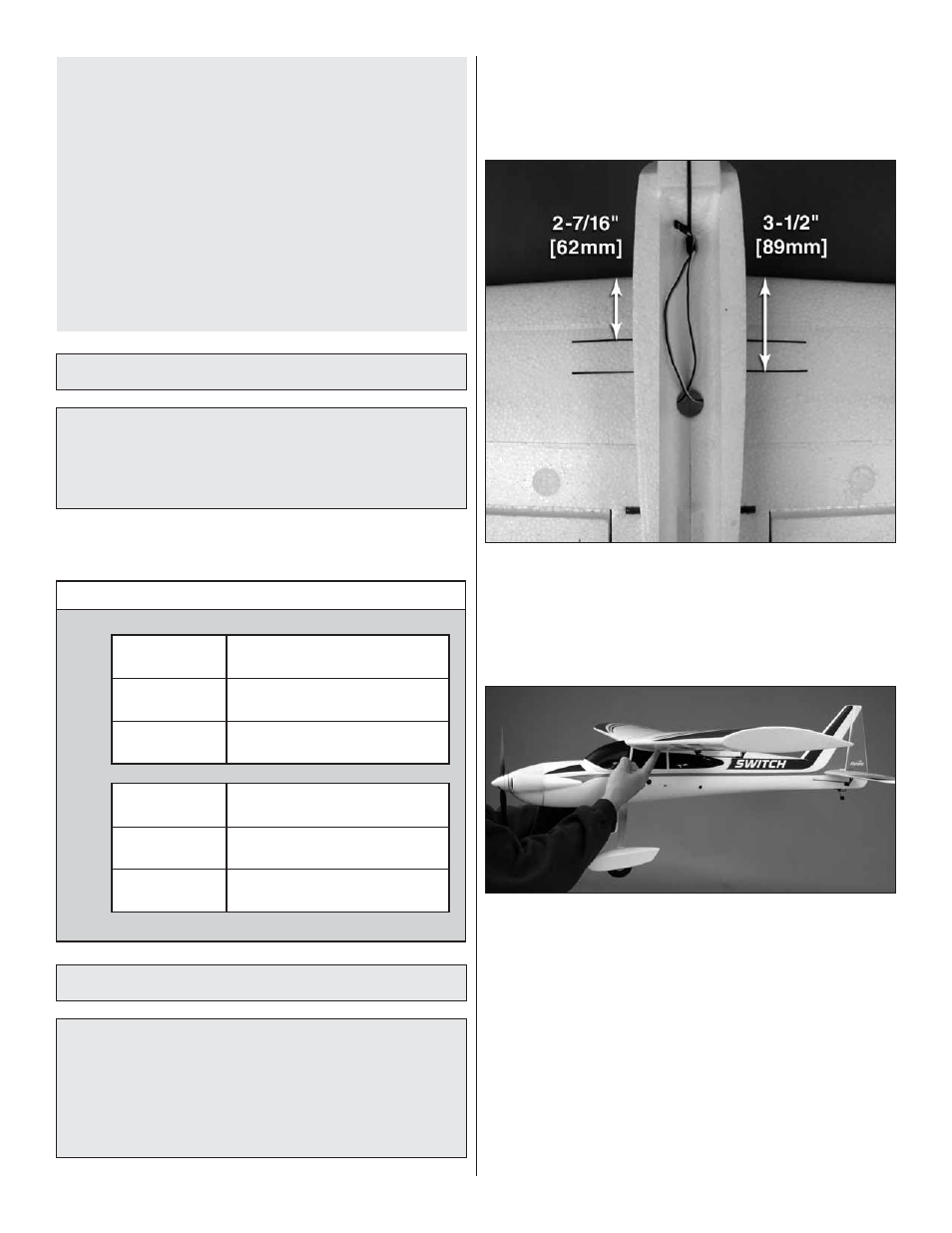
❏
1. Apply narrow (1/16" [2mm]) strips of tape 2-7/16"
[62mm] from the leading edge of each wing panel onto the
underside of the wings as shown (you can also apply some
masking tape and draw the lines with a felt-tip pen). Apply
another pair of tape strips 3-1/2" [89mm] from the leading
edge of the wing panels.
❏
2. With the wings attached to the fuselage, all parts of
the model installed (ready to fl y) and the battery installed, lift
the model with two fi ngers within the tape lines you applied.
❏
3. Shift your fi ngers forward or aft between the tape lines
until the model balances level on your fi ngertips. If you cannot
balance the model between the tape lines, you will need to
shift the battery and/or receiver forward or aft within the
fuselage. If the tail continues to drop even with your fi ngers
all the way at the aft tape lines, the model is “tail heavy”. You
will need to move the battery pack and/or receiver forward. If
the nose continues to drop even with your fi ngers all the way
to the forward lines, the model is “nose heavy”. You will need
to move the battery pack and/or receiver forward.