Flintec – Flintec FAD-4 User Manual
Page 6
FLINTEC
Document
Date
Code
Rev.
Page
FAD - 4 DIGITAL LOADCELL JUNCTION BOX
02.05.00
FAD4_2RM
2
6 of 20
FILE TYPE DESCRIPTION
Calibration and weight parameters are protected by calibration lock devices hardware and software.
If the CALIBRATION LOCK is activated, weight parameter/ calibration file types are not accessible.
The “CAL LOCK” is a hardware jumper inside the DJB required by Weights & Measures authorities
so that calibration can be sealed (jumper inserted).
The “PINLOCK” is a software Personal Identification Number, which ensures that no accidental
scale calibration is attempted. The “PIN LOCK” and the “CAL LOCK” are logically connected.
In addition to the “CAL LOCK” an A.T.CNT (Audit Trail Counter) is provided for use by
Weights and Measures Authorities.
The A.T.CNT (6 digits) is incremented when a weight parameter is changed, or a corner / scale
calibration is attempted, regardless if the changes are saved in EEPROM or not.
The position of the “CAL LOCK” jumper and the A. T. CNT number may be inspected with
Fn 48 (chapter 6).
The A.T.CNT may be viewed by the Weight & Measures to verify that no calibration constants have
been altered since the inspection/stamping date .
To avoid wait time in certain commands, (especially when units are connected in a network), the
DJB will not respond to the command issued but on subsequent polls by command “?”.
? UPLOAD STATUS
It is the main command used to poll the FAD(s), which reply with the current weight being
measured or with a message if bit0 of status byte is ‘1’. In the normal state the FAD-4 will respond
within 3-4 character time. (e.g. with 9600baud, the character time
≈
1 msec, the master should
expect reception of STX from the FAD-4 within 5 msec after the ETX was transmitted from the
master).
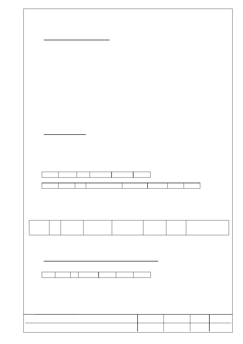
Master transmission
STX
ADD ? BCS2 BCS1
ETX
Slave response
STX ADD X STATUS
BYTE WEIGHT BCS2 BCS1
ETX
where X= ‘?’ if there is new A/D conversion since the last weight value transmission.
X=’ ’ if there is no new A/D conversion since the last weight value transmission.
and WEIGHT: 5 digits + decimal point if any.(ASCII,MSD FIRST)
STATUS BYTE
b7 b6
b5 b4
b3
b2 b1 b0
Zero or
Parity
1 Sign
of
weight
0=+ 1=-
No Motion
0=NO,
1=YES
Out of Range
0=NO
1=YES
Autozero
0=NO
1=YES
0=Gross
1=Net
0=Normal Weight
1=No Weight Display
The WEIGHT field will contain a message if b0 of the status byte is high.
A . DEAD LOAD CALIBRATION (ELECTRONIC mV/V)
Downloads the total mV/V output of the empty scale for dead load calibration.
Master transmission :
STX ADD A yyyyyy BCS2 BCS1 ETX
yyyyyy : 6 digits of mV/V multiplied by 10000 (ASCII decimal).
Poll the slave by using command ‘?’. Possible response messages: ‘WAIT..’ or ‘ERR 91’.
Slave returns to normal Weight output after the command is completed.
THE VALUE IS NOT SAVED IN EEPROM UNTIL A STORE COMMAND IS ISSUED.