Flintec – Flintec FAD-4 User Manual
Page 13
FLINTEC
Document
Date
Code
Rev.
Page
FAD - 4 DIGITAL LOADCELL JUNCTION BOX
02.05.00
FAD4_2RM
2
13 of 20
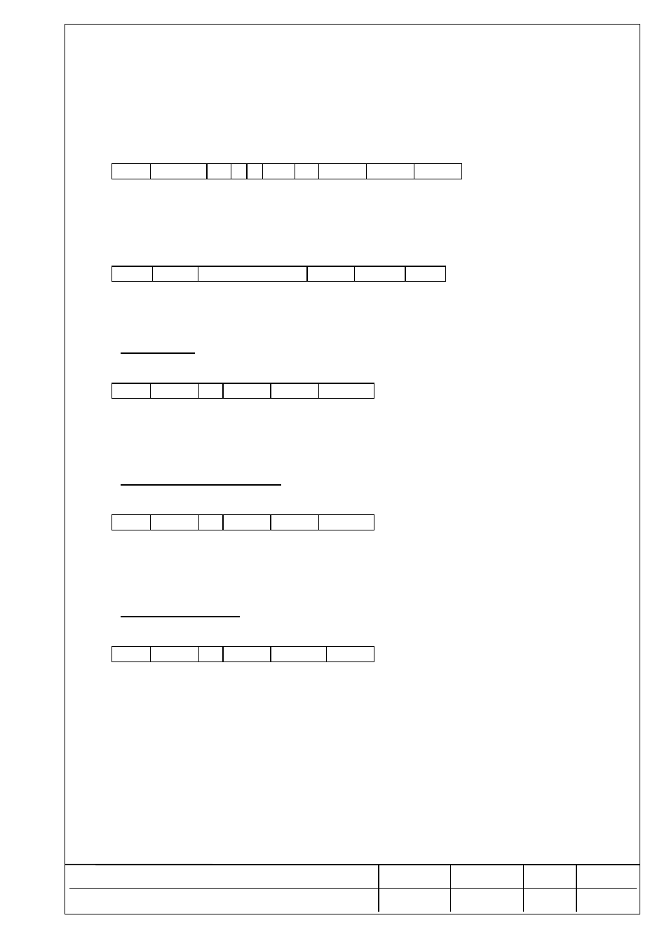
Master transmission: (SETUP 2)
STX ADD S 2
a
bb cc BCS2 BCS1 ETX
a :
Slave address (A - Z)
bb :
Baudrate :
24 = 2400 baud
96 = 9600 baud
19 = 19200 baud
38
=
38400baud
57=57600baud
11=115200baud
cc :
Data bits / parity :
17 = 7 data bits even parity
08 = 8 data bits, no parity.
Slave response:
STX
ADD
ACK or NAK
BCS2
BCS1
ETX
New settings of baud rate , data bits and parity are not in effect until a write command ‘W’ is issued.
T :
TARE
Tares the weight on the scale and switches the FAD-4 to net weight mode.
Master transmission:
STX ADD T BCS2 BCS1 ETX
Slave response: NONE.
Execution of the command should be checked by examining the next status string.
W :
WRITE TO EEPROM
Writes setup, parameters, setpoint values, calibration data to EEPROM and resets slave.
Master transmission:
STX ADD W BCS2 BCS1 ETX
Slave response: NONE.
WARNING : The max number of write cycles allowed is 100.000.
Z :
ZERO SCALE
Sets the scale to zero if zero conditions are met (stable weight within 2% of scale capacity) .
Master transmission:
STX ADD Z BCS2 BCS1 ETX
Slave response: NONE.
Execution of the command should be checked by examining the next status string.