FingerTec m-Kadex Installation Guide User Manual
Page 3
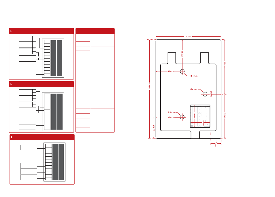
Diagram1 • Normally Close (NC)
Diagram 2 • Normally Open (NO)
Diagram 3 • Other Accessories
EM Lock (NO)
+
---
Emergency Break 1
Glass (Type NO) 3
Overwrite Switch B
(Type NO)
D
Release Button
DC12V 3A
Power Supply
ALM+
ALM-
NC
COM
NO
BUT
GND
SEN
BEL+
BEL-
GND
+12V
ALM+
ALM-
NC
COM
NO
BUT
GND
SEN
BEL+
BEL-
GND
+12V
Alarm device Type
NO or NC Dry contact
Door Sensor
Doorbell
DC12V 3A
Power Supply
EM Lock (NC)
+
---
Emergency Break 2
Glass (Type NC) 3
Overwrite Switch A
(Type NC)
C
Release Button
DC12V 3A
Power Supply
ALM+
ALM-
NC
COM
NO
BUT
GND
SEN
BEL+
BEL-
GND
+12V
Appendix II
Terminal Dimensions and Measurements
Appendix I
Power Supply & Door Lock System
Wiring Diagrams
Front View of m-Kadex
Door Lock Connectors
The terminal will trigger the alarm
output (NO or NC) for the follow-
ing situations:
• Door forced open (A door sen-
sor must first be installed)
• Door open time out (A door sen-
sor must first be installed)
• Terminal has been illegally dis-
mantled
Alarm System
(NO or NC Type – Check
in Advance Options)
Dry Contact (independ-
ent power supply for door
lock)
• NO type door lock (NO1-
COM)
• NC type door lock (NC1-
COM)
Power Contact (using
power from terminal to
power on door lock)
• NO type door lock (NO1-
GND)
• NC type door lock (NC1-
GND)
Dry Contact (independ-
ent power supply for door
lock)
• NO type door lock (NO1-
COM)
• NC type door lock (NC1-
COM)
Power Contact (using
power from terminal to
power on door lock)
• COM1 - +12V
Door Sensor
(SEN-GND)
Release button
(BUT-GND)
Door Bell
WIRING PORT USAGE
ALM+
ALM-
NC
NO
COM
BUT
GND
SEN
BEL-
BEL+