Front view of i-kiosk 100, Door lock connectors – FingerTec i-Kiosk 100 Installation Guide User Manual
Page 3
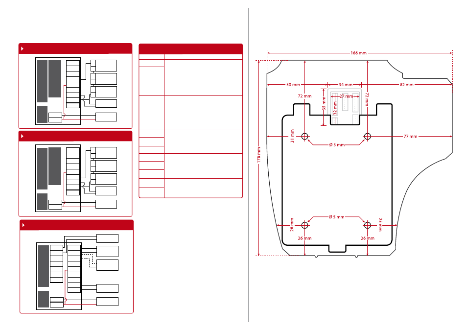
Diagram1 • Normally Close (NC)
Diagram 2 • Normally Open (NO)
Diagram 3 • Other Accessories
NC2
COM2
NO2
NC1
COM1
NO1
BUT
GND
SEN
GND
+12V
DC12V
Electronic Door
Lock (Type NC)
Emergency
Break Glass
(Type NC)
Overwrite
Keyswithch
(Type NC)
Push Release
Button
DC12V 3A
Power Supply
+
_
2
3
A
C
NC2
COM2
NO2
NC1
COM1
NO1
BUT
GND
SEN
GND
+12V
DC12V
Electronic Door
Lock (Type NO)
Emergency
Break Glass
(Type NO)
Overwrite
Keyswithch
(Type NO)
Push Release
Button
DC12V 3A
Power Supply
+
_
1
3
B
D
*Door Sensor, Alarm, Doorbell.
NC2
COM2
NO2
NC1
COM1
NO1
BUT
GND
SEN
GND
+12V
Doorbell
Alarm Device
Type NC dry
contact
Alarm Device
Type NO dry
contact
Door Sensor
DC12V 3A
Power Supply
BEEL+
BEEL-
BEEP
GLED
RLED
INWD0
INWD1
Use either Type NO or Type NC alarm device.
Front View of i-Kiosk 100
Appendix II
Terminal Dimensions and Measurements
Appendix I
Power Supply & Door Lock System Wiring Diagrams
Door Lock Connectors
The terminal will trigger the alarm output (NO or NC)
for the following situations:
• Door forced open (A door sensor must first be in-
stalled)
• Door open time out (A door sensor must first be in-
stalled)
• Terminal has been illegally dismantled
Dry Contact
(Independent power supply for door lock)
• NO type door lock (NO1-COM)
• NC type door lock (NC1-COM)
Power Contact
(Using power from terminal to power on door lock)
• NO type door lock (NO-GND)
• NC type door lock (NC-GND)
Dry Contact
(Independent power supply for door lock)
• NO type door lock (NO1-COM)
• NC type door lock (NC1-COM)
Power Contact
(Using power from terminal to power on door lock)
• COM1 - +12V
Alarm System
NO Type – NO2 – COM2
NC Type – NC2- COM2
Door Sensor (SEN-GND)
Release Button(BUT-GND)
Door Bell
WIRING PORT USAGE
NO1
NC1
COM1
NO2
COM2
NC2
SEN
GND
BUT
Bell+
Bell-