Marking body tubes, Prepare tail cone and adapter, Assembling engine mount and tail cone – Estes 2053 - Paveway User Manual
Page 3: Assembling lower fins, Fin tu be m ar kin g g uid e mat ch lin es
"LL"
3
.
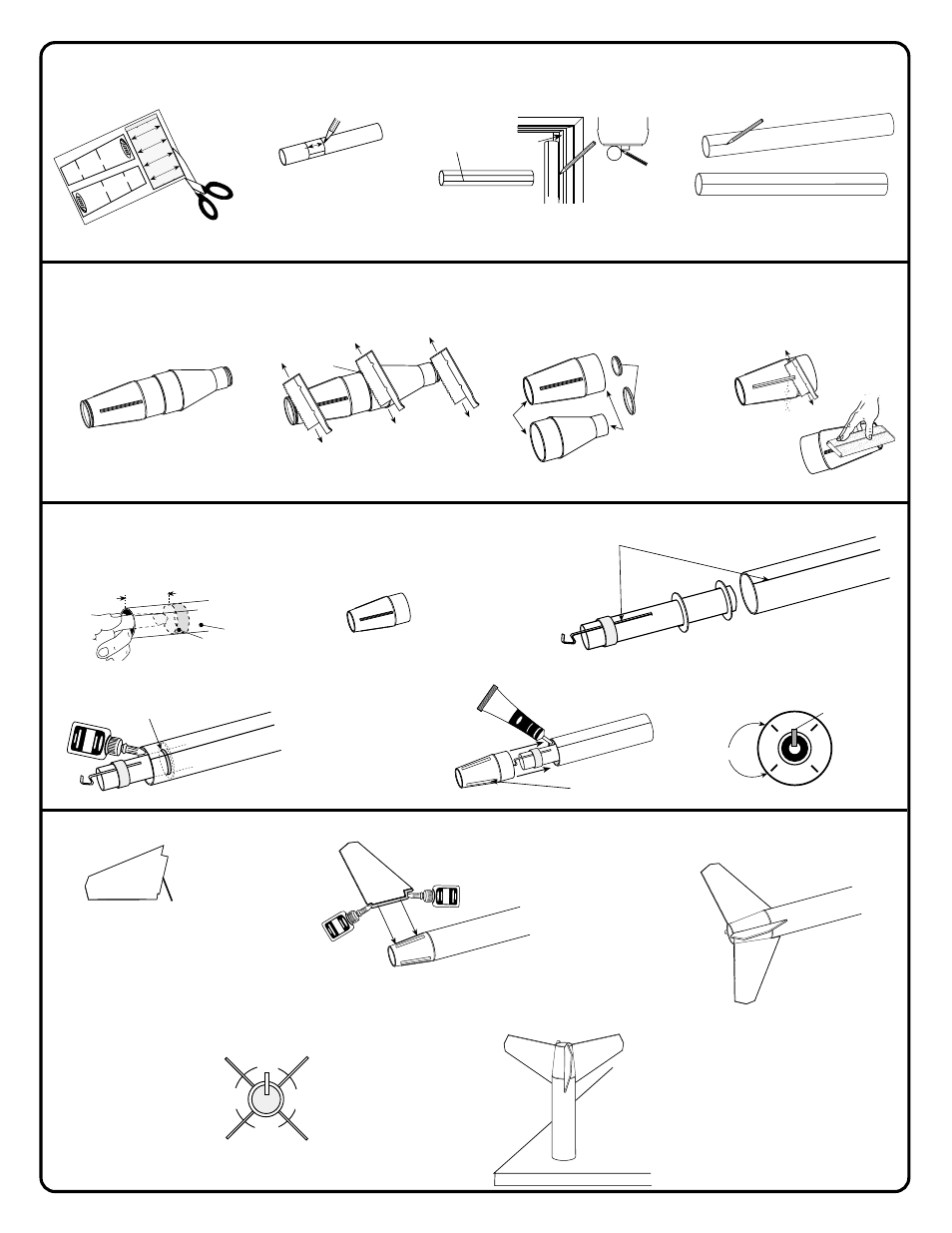
MARKING BODY TUBES
SHOCK CORD
MOUNT
S
E
C
TIO
N
3
S
EC
TIO
N
2
S
E
C
TIO
N
1
SHOCK CORD
MOUNT
SECTION
3
SECTION
2
SECTION
1
FIN
FIN
FIN
FIN
TU
BE
M
AR
KIN
G G
UID
E
MAT
CH
LIN
ES
UPPER TUBE
M
ARKING
G
U
IDE
GB
U-24 P
A
VEW
A
Y
III EST 2053
4
.
PREPARE TAIL CONE AND ADAPTER
DISCARD
Sand edges smooth.
A
.
Test fit fin tabs in slots.
Sand as needed for
proper fit.
C
.
Check alignment of fins as
shown. Allow glue to set.
D
.
Stand rocket on flat table
until glue dries completely.
NOTE
:
Fin
shape and
tab location.
BT-20
Upper Body Tube
A
.
Cut out tube marking
guide.
B
.
Wrap tube marking guide around
upper body and mark four places.
C
.
Extend all lines entire length
of tube.
D
.
Place a pencil mark on the
larger tube for launch lug "LL".
A
.
Tail Cone and Adapter
B
.
Using a razor saw, carefully cut off
ends and cut in half.
C
.
Sand edges smooth
.
D
.
Carefully saw off nibs. Sand away
excess plastic lip flush with surface.
Upper Body Tube
Top view
Door
Frame
Fin lines
Extend Launch Lug line
with pencil.
Main Body Tube BT-55 (1)
Cut in half.
NOTE: Fins must be attached
correctly for stable flight.
5
.
ASSEMBLING ENGINE MOUNT AND TAIL CONE
A
.
Use finger to smear glue 2 3/4" (70 mm)
inside rear of body tube.
B
.
Engine hook must line up with
launch lug "LL" line.
DO NOT CEMENT
TAIL CONE YET!
C
.
Insert engine mount inside body tube
and push into place with tail cone.
Remove tail cone immediately. Let dry.
D
.
Apply a glue fillet around ring and
body tube joint. Let dry.
E
.
Apply plastic cement around
inside of body tube. Align
Launch Lug line between
fin slots on tail cone. Push
tail cone into body
completely. Let dry.
Fin Slot
Engine Hook
Rear View
Fin Slots
MAIN BODY TUBE
Glue
Body
Tube
"LL"
Fins should project
straight from the body.
6
.
ASSEMBLING LOWER FINS
90˚
90˚
90˚
90˚
Tab
PLASTIC
CEMENT
"LL"
"LL"
Cut off.
2 3/4”
(70 mm)
Cut off.
GLUE
"LL"
B
.
Apply carpenter's glue to fin and tab
edge. Push fin into tail cone. Let dry.
Continue to assemble remaining fins.
Let dry.
GLUE
GLUE