8installing the dle-170 on your airplane – DLE 170 User Manual
Page 8
8
Installing the DLE-170 on Your Airplane
Note: The DLE-170 must be installed on at least a 3/8" [9.5mm]
fi rewall. The fi rewall must be securely glued to the airplane. Use
triangle stock and pin the fi rewall with hardwood dowels to
reinforce the fi rewall glue joints. Never install the DLE-170 onto
a fi rewall thinner than specifi ed because it may fail due to the
power of the engine.
Note: The distance from the fi rewall to the propeller washer is
8.34" [212mm].
1. Use the supplied template (on the back cover of this manual) to
drill the engine mounting bolt holes.
2. Install (4) 6mm blind nuts or tee
nuts (not included) into the back
side (non-engine side) of the fi rewall.
Install the engine to the fi rewall
using (4) 6x45mm SHCS with 6mm
lock washers and fl at washers (not
included) with the included standoffs. Use some threadlocking
compound, such as Great Planes
®
Pro
™
Threadlocker (GPMR6060)
on the screws where the threads enter the blind nuts.
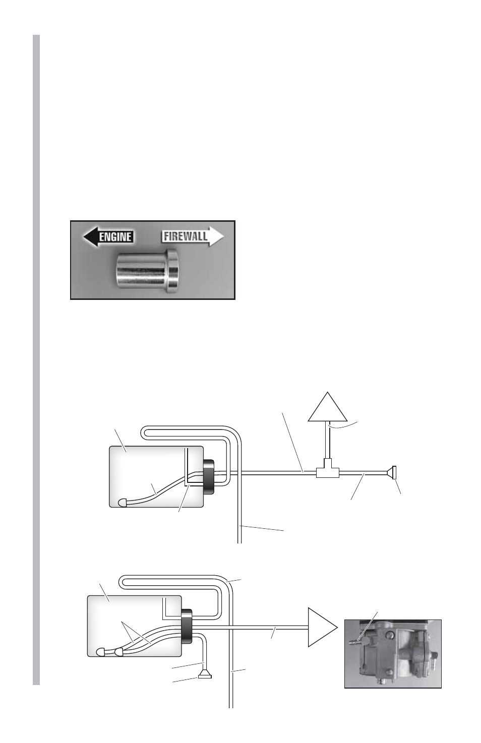
3. Install the fuel tank in the airframe. Use only gasoline-safe fuel
lines and a gasoline safe stopper.
Drain/Vent Pressure Relief Line
Route to top-front of fuel tank interior,
to prevent siphoning.
T-Fitting
Carb
Clunk Line
Fuel Tank
Filler Cap
or Plug
Supply Line
to T-Fitting
Make connection line
between T-Fitting and
Carburetor as short
as possible.
Fuel fill line
This line must be extended
to exit the bottom of the aircraft.
2-LINE SET UP
Drain/Vent Pressure Relief Line
Route to top-front of fuel tank
interior, to prevent siphoning.
Carb
Clunk Lines
Fuel Tank
Carburetor Fuel Inlet
Plug
Supply Line
to Carburetor
Fuel fill line
This line must be
extended to exit the
bottom of the aircraft.
3-LINE SET UP