DLE 170 User Manual
Page 7
7
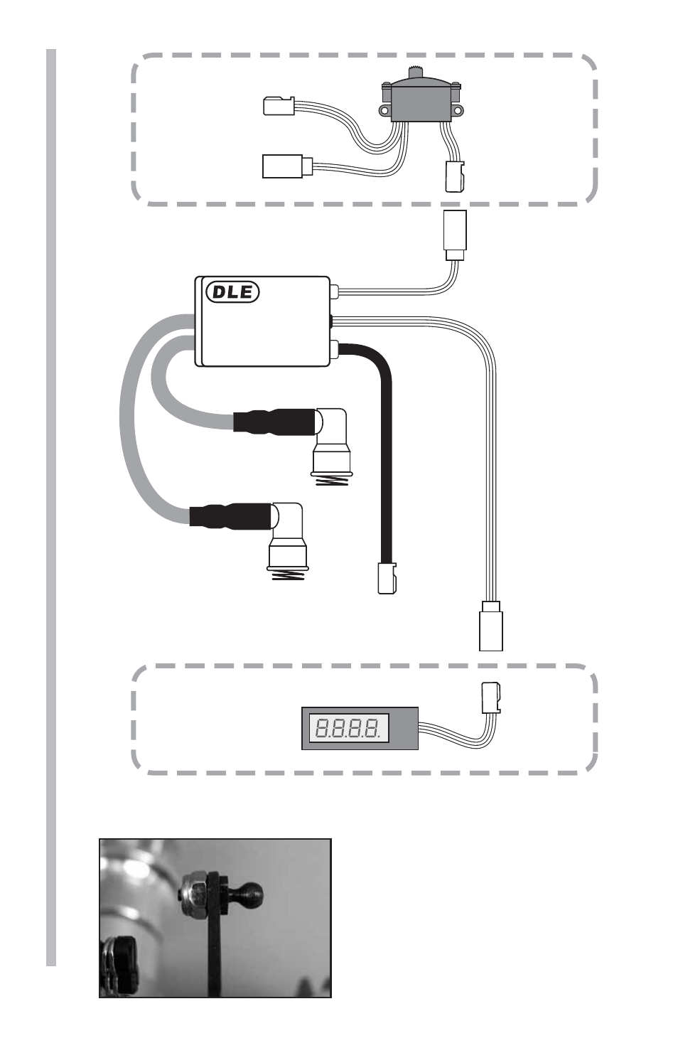
Ignition Wires
(To Spark Plugs)
Ignition Control
Switch Wire
(To On/Off Switch)
Pick-Up
Sensor Wire
(To Sensor On Engine)
Tachometer
Lead/
RPM
Signal
Out-Put
ELECTRONIC IGNITION
SYSTEM
Battery Lead
Charge Lead
Switch
(Not included)
Optional
Tachometer
(Not included)
7. Use the above diagram to install the Electronic Ignition Module
to the engine.
8. Install a 2-56 ball links (not
included) to the throttle & choke
control arms. Use a 2-56 lock nut
to secure the ball links or use (2)
2-56 nuts and thread locker to secure
the links. Once the links are secure,
exercise the throttle and choke levers
to ensure that no binding occurs.