Digilent Robotic Development Kit User Manual
Page 9
Line Sensor Robotic Development Kit Reference Manual
www.digilentinc.com
page 9 of 9
Copyright Digilent, Inc. All rights reserved. Other product and company names mentioned may be trademarks of their respective owners.
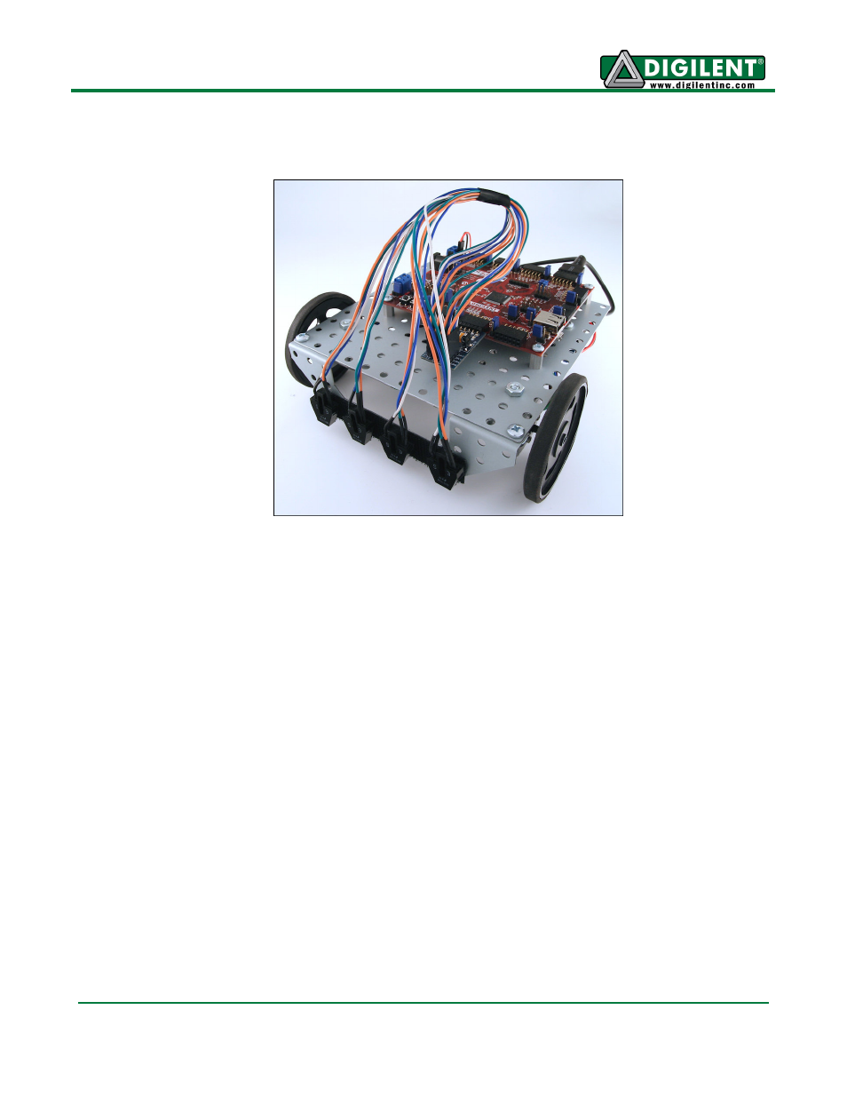
16. Attach the four IROS to the bent bracket from left to right using the attached Velcro, and
connect the sensors in the same order, respectively, to each of the headers (S4-S1) on the
PmodLS1.
MPLAB can now be used to program the RDK_LineSensor reference design to the board. For
more information on how to program the Cerebot MX4cK using MPLAB, see the Cerebot MX4cK
LED Demo project at www.digilentinc.com. Note that running the reference design that turns the
motors requires that the power select mode jumper J12 be shorted to External Power. Note that
the recommend surface for running the reference design is a white surface with black tape.
Once the board has been programmed with the reference design, place the robot on the
recommended surface with a black line between the two middle sensors. Turn the board on and
press button 2 to cause the motors to turn and observe the robot follow the black line. Press
button 1 to stop the robot.