Digilent PmodCON2 User Manual
Digilent Hardware
D
D
i
i
g
g
i
i
l
l
e
e
n
n
t
t
P
P
m
m
o
o
d
d
C
C
O
O
N
N
2
2
™
™
M
M
o
o
d
d
u
u
l
l
e
e
B
B
o
o
a
a
r
r
d
d
R
R
e
e
f
f
e
e
r
r
e
e
n
n
c
c
e
e
M
M
a
a
n
n
u
u
a
a
l
l
®
w w w . d i g i l e n t i n c . c o m
Revision: 04/12/05
215 E Main Suite D | Pullman, WA 99163
(509) 334 6306 Voice and Fax
Doc: 502-066
page 1 of 1
Copyright Digilent, Inc. All rights reserved. Other product and company names mentioned may be trademarks of their respective owners.
Overview
The Digilent PmodCON2 Module Board (the CON2™)
makes it easy to connect a Digilent system board to
outside devices with BNC plugs. It is ideal for testing a
Digilent system board with equipment that uses BNC
connections.
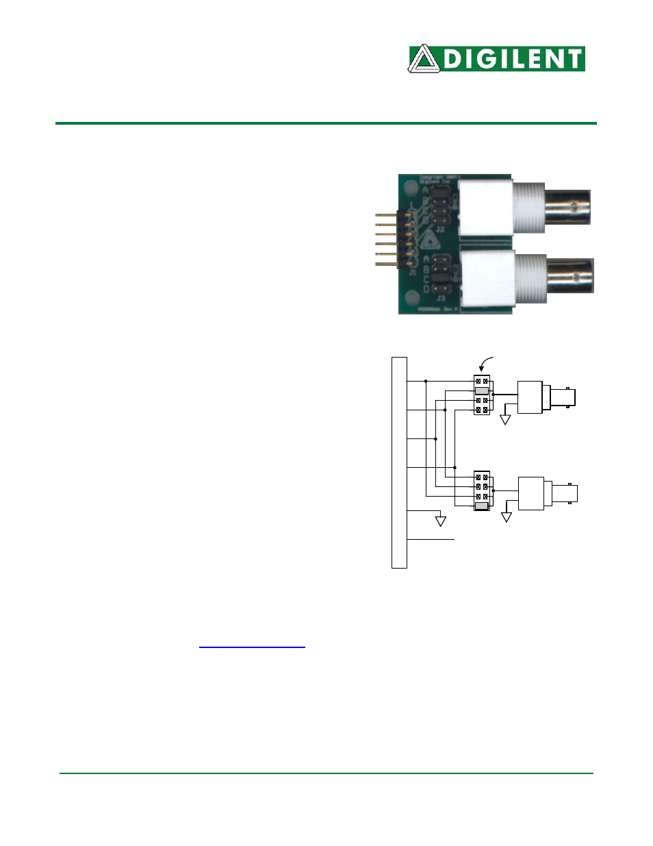
The CON2 conveys signals between a 6-pin header
and two BNC jacks. It uses jumpers to specify which of
the 6-pin connector pins correspond to each BNC jack.
Features include:
• a 6-pin header
• two BNC jacks
• two jumper shorting block systems
• small form factor (2.06” x 1.44”).
Functional Description
Each BNC connector on the CON2 has four clearly-
labeled jumper pins that correspond to the four available
pins on the 6-pin header. When the shorting block is
placed on a jumper pin, the related pin in the 6-pin
header then corresponds to the BNC jack.
The CON2 has a 6-pin header for easy connection to a
Digilent system board. Some system boards, like the
Digilent Pegasus board, have a 6-pin header that can
connect to the CON2 with a 6-pin cable. To connect the
CON2 to other Digilent system boards, a Digilent
Modular Interface Board (MIB) and a 6-pin cable may be
needed. The MIB plugs into the system board, and the
cable connects the MIB to the CON2.
For more information see,
www.digilentinc.com
.
P6
P5
Vcc
P4
P2
P1
P3
CON2 Circuit Diagram
BNC 1
BNC 2
J1 Conn
ec
to
r
Jumper Blocks For
Signal Routing