Digilent NXVGA User Manual
Digilent Hardware
D
D
i
i
g
g
i
i
l
l
e
e
n
n
t
t
N
N
X
X
V
V
G
G
A
A
R
R
e
e
f
f
e
e
r
r
e
e
n
n
c
c
e
e
M
M
a
a
n
n
u
u
a
a
l
l
®
w w w . d i g i l e n t i n c . c o m
Revision: November 9, 2006
215 E Main Suite D | Pullman, WA 99163
(509) 334 6306 Voice and Fax
Copyright Digilent, Inc. All rights reserved
12 pages
Doc: 502-107
P16
Spartan 3
FPGA
RED
GRN
BLU
HS
VS
512
P15
T7
R5
1K
2K
3K
N15
512
J16
K16
K15
1K
2K
3K
L15
512
M16
M15
N16
1K
2K
3K
P16
P16
200
200
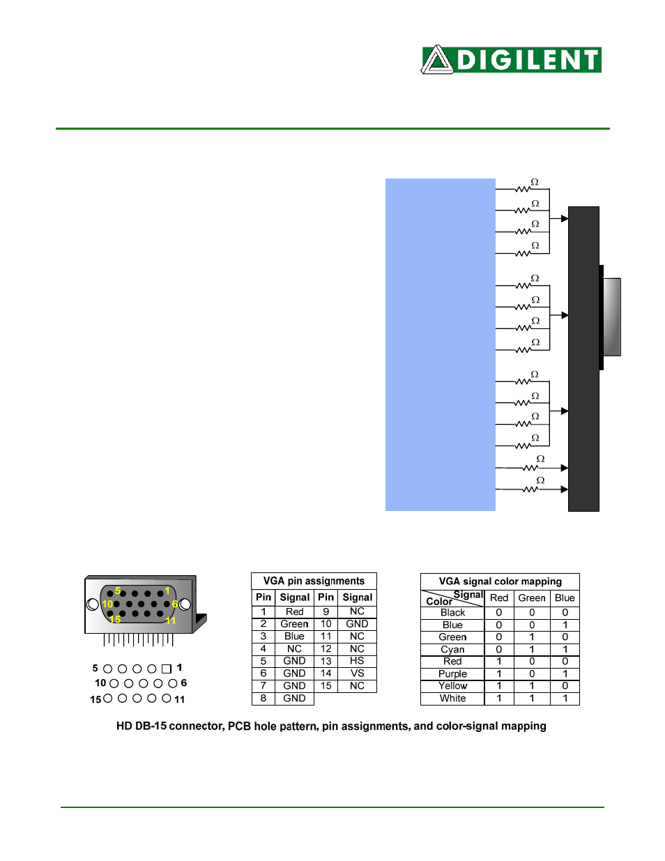
Nexys VGA Module
Block Diagram
Overview
The Digilent Nexys VGA Module provides a 12bit VGA
interface for use with the Digilent Nexys board. The 12
bit interface allows up to 4096 colors displayed on a
standard VGA Monitor.
The Nexys VGA Module interfaces with the Nexys board
via the 16 pin header at J8 and connects to a VGA
monitor using a standard 15 pin VGA cable.
Functional Description
VGA Port
The five standard VGA signals Red, Green, Blue,
Horizontal Sync (HS), and Vertical Sync (VS) are routed
directly from the FPGA to the VGA connector. There are
four signals routed from the FPGA for each of the
standard VGA color signals resulting in a video system
that can produce 4,096 colors. Each of these signals
has a series resistor that when combined in the circuit,
form a divider with the 75-ohm termination resistance of
the VGA display. These simple circuits ensure that the
video signals cannot exceed the VGA-specified
maximum voltage, and result in color signals that are
either fully on (.7V), fully off (0V) or somewhere in
between.
VGA signal timings are specified, published, copyrighted and sold by the VESA organization
(www.vesa.org). The following VGA system timing information is provided as an example of how a