Digilent 6014-210-000-KIT User Manual
Digilent Hardware
8
8
0
0
5
5
1
1
T
T
r
r
a
a
i
i
n
n
e
e
r
r
B
B
o
o
a
a
r
r
d
d
R
R
e
e
f
f
e
e
r
r
e
e
n
n
c
c
e
e
M
M
a
a
n
n
u
u
a
a
l
l
®
w w w . d ig i l en t inc . c om
Revision: September 24, 2008
Note: This document applies to REV A of the board.
215 E Main Suite D | Pullman, WA 99163
(509) 334 6306 Voice and Fax
Doc: DSD-0000262
page 1 of 4
Copyright Digilent, Inc. All rights reserved. Other product and company names mentioned may be trademarks of their respective owners.
Overview
The 8051 board is a useful tool for embedded
control and robotics projects for both students
and hobbyists.
Its versatile design and programmable
microcontroller lets you access numerous
peripheral devices and program the board for
multiple uses. The board has many I/O
connectors and supports a number of
programming options including 8051
assembly and C
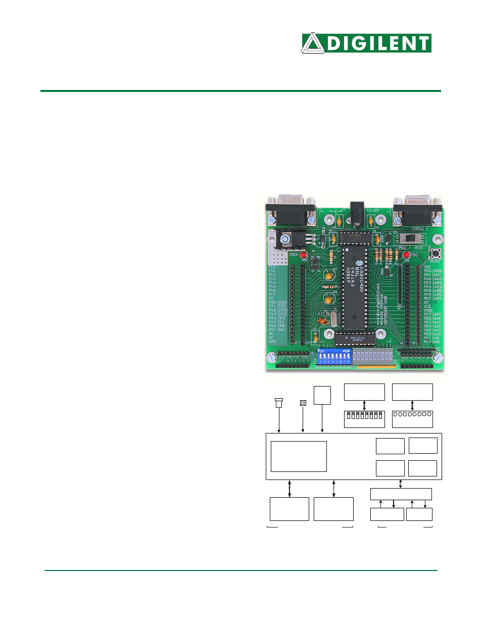
The 8051 trainer board has 8 switches and 8
buffered LEDs for connection to the
microcontroller, bread board or peripheral
devices. It provides access to pins of the
8051 through sip male and female
connectors for wiring to bread board or
attaching Digilent Pmod™ peripheral
modules. Digilent peripheral modules include
H-bridges, analog-to-digital and digital-to-
analog converters, speaker amplifier,
switches, buttons, LEDs, as well as
converters for easy connection to screw
terminals, BNC jacks, servo motors, and
more.
Features include:
•
A Maxim Semiconductor DS89C450
microcontroller (an 8051/52) with 64K
bytes of on-chip Flash memory.
•
Eight on-board Switches accessible
via both male and female connector
•
Eight on-board LEDs accessible via
both male and female connector
•
an on-board voltage regulator (in
some versions)
•
two 20-pin male and female
connectors allowing access to all
8051 ports of P0, P1, P2, and P3 for
connection to external devices such
as bread board or Digilent peripheral
module boards.
•
support for the Maxim on-chip serial
programmer
•
two RS232 compatible Serial ports
with DB9 connectors
•
An small bread board can be screwed
on the board to insert any external IC
and connect it to the board
20-Pin male and
female connectors
P0 and P2
DS89C450
(DS89C440)
(DS89C430)
40 male and female connectors
11.0592
MHz
crystal
64KB Flash
(32KB Flash)
(16KB Flash)
(internal)
Reset
button
8 LEDs
Three 16 bit
counters
2 USART
ports
Power
connectors
16
MAX232
1KB SRAM
(Internal)
20-Pin male and
female connectors
P1 and P3
16
DB9 Connector
(Programmer)
DB9
Connector
2 DB9 connectors
8-Pin male and
female connectors
8
8 Switches
8-Pin male and
female connectors
8
4
RX1
TX1
RX0
TX0
Internal 256B
scratchpad
RAM
8051 Trainer Circuit Diagram