Digilent AIO1 User Manual
Page 2
AIO1 Reference Manual
Digilent, Inc. ™
www.digilentinc.com
Page
2
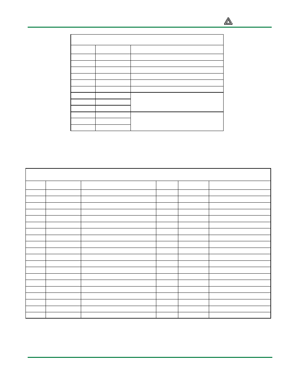
J2 connector pin definitions
J2 pin
AIO signal
Description
30
DACIN
AD7303 data input
31
DACLK
AD7303 clock input
29
SYNC
AD7303 Sync signal
34
ADOUT
AD7823 data output
33
CONVST
AD7823 clock input
32
ADCLK
AD7823 convert start signal
38
DIN0
35
DIN1
36
DIN2
Uncommitted digital inputs
28
DOUT0
27
DOUT1
19
DOUT2
Uncommitted digital outputs (use
caution – do not drive above 3.3V)
The breadboard connector signals are shown in the following table. The breadboard connector allows
various AIO1 signals to be connected to the breadboard using jumper wires. Signals from the BNC
connectors (J5 and J8), the RCA connectors (J6 and J9), and the audio connectors (J7 and J10) are
available, as well as signals from the op-amps and data converters.
Breadboard Connector (J11) Signal Definitions
J11 pin
Signal
Definition
J11 pin
Signal
Definition
1
VCC33
Regulated voltage
21
OP2AO
Op-amp 2A output
2
VU
Unregulated voltage
22
OP2BO
Op-amp 2B output
3
DI0
Uncommitted digital input
23
OP2BI+
Op-amp 2B input +
4
DO0
Uncommitted digital output
24
OP2BI-
Op-amp 2B input -
5
DI1
Uncommitted digital input
25
OP1BI+
Op-amp 1B input +
6
DO1
Uncommitted digital output
26
OP1BI-
Op-amp 1B input -
7
DI2
Uncommitted digital input
27
OP1BO
Op-amp 1B output
8
DO2
Uncommitted digital output
28
OP1AO
Op-amp 1A output
9
J8P
BNC post connection
29
OP1AI+
Op-amp 1A input +
10
J8S
BNC shield connection
30
OP1AI-
Op-amp 1A input -
11
J9P
RCA center connection
31
GND
System ground
12
J9S
RCA shield connection
32
ADCREF
ADC reference voltage
13
J10P
Audio tip connection
33
ADCIN+
ADC input +
14
J10S
Audio ring connections
34
ADCIN-
ADC input -
15
DACOUTA
DAC channel A output
35
J7P
Audio tip connection
16
DACOUTB
DAC channel B output
36
J7S
Audio ring connections
17
DACREF
DAC reference voltage
37
J6P
RCA center connection
18
GND
System ground
38
J6S
RCA shield connection
19
OP2AI+
Op-amp 2A input +
39
J5P
BNC post connection
20
OP2AI-
Op-amp 2A input -
40
J5S
BNC shield connection