Digilent 410-310P User Manual
Page 2
PmodRS485™ Reference Manual
Copyright Digilent, Inc. All rights reserved.
Other product and company names mentioned may be trademarks of their respective owners.
Page 2 of 3
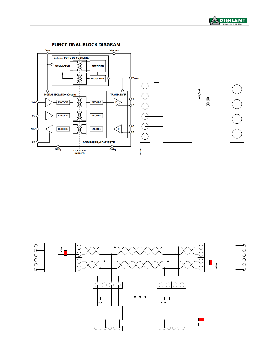
Figure 1. Functional block diagrams of PmodRS485.
Multiple PmodRS485 devices can be chained together up to 256 nodes in total. When two PmodRS485s are
connected, JP1 should be loaded on both devices. When more than two PmodRS485s are connected, JP1 should
only be loaded on the two devices at the terminating ends of the wire, and stubs off of the main line should be
kept as short as possible (see Figs. 2 & 3 below).
The PmodRS485 has two control signals: receiver enable (RE) and driver enable (DE). RE enables the receiver
module when driven low, and disables it when driven high. DE has the opposite polarity and enables the driver
module when driven high, and disables it when driven low.
For comprehensive electrical characteristics of this device, refer to the ADM2582E datasheet available from Analog
Devices.
RS485
JP1
Z
Y
A
B
RS485
JP1
Z
Y
A
B
RS
485
JP1
Z
Y
A
B
RS485
RS
485
JP1
Z
Y
A
B
RS485
Shorted jumper
Not Shorted Jumper
Figure 2. Full-duplex communication.
RS485
Transceiver
RE
DE
TXD
RXD
GND
VCC
JP1
Y-output
Z-output
B-input
A-input