Digilent 410-222P User Manual
Page 2
PmodOLED Reference Manual
www.digilentinc.com
page 2 of 2
Copyright Digilent, Inc. All rights reserved. Other product and company names mentioned may be trademarks of their respective owners.
Interface
The display has a D/C pin (display or
command select) that determines whether
bytes sent to the display are interpreted as
commands or as display data. The D/C pin is
set high for display buffer access and low for
command access.
The RES pin is used to reset the SSD1306
display controller. The RES pin is driven low
for reset and driven high for normal operation.
The low-going reset pulse must be a minimum
of 3us (microseconds) in duration for the
display controller to reset correctly.
The UG2832 display is a serial device that is
accessed using SPI. It is a write-only device,
so it is not possible to read the display buffer
contents or status from the panel. The
maximum SPI clock frequency is 10Mhz. The
CS (Chip Select) pin has to be held low for the
display to receive data over the SPI interface.
Digilent has libraries for the PmodOLED that
provide functions for initializing the display and
rendering simple text and graphics onto the
display. These libraries can be used as-is or as
a starting point for a more sophisticated
graphics library. They are available on the
PmodOLED product page at
www.digilentinc.com.
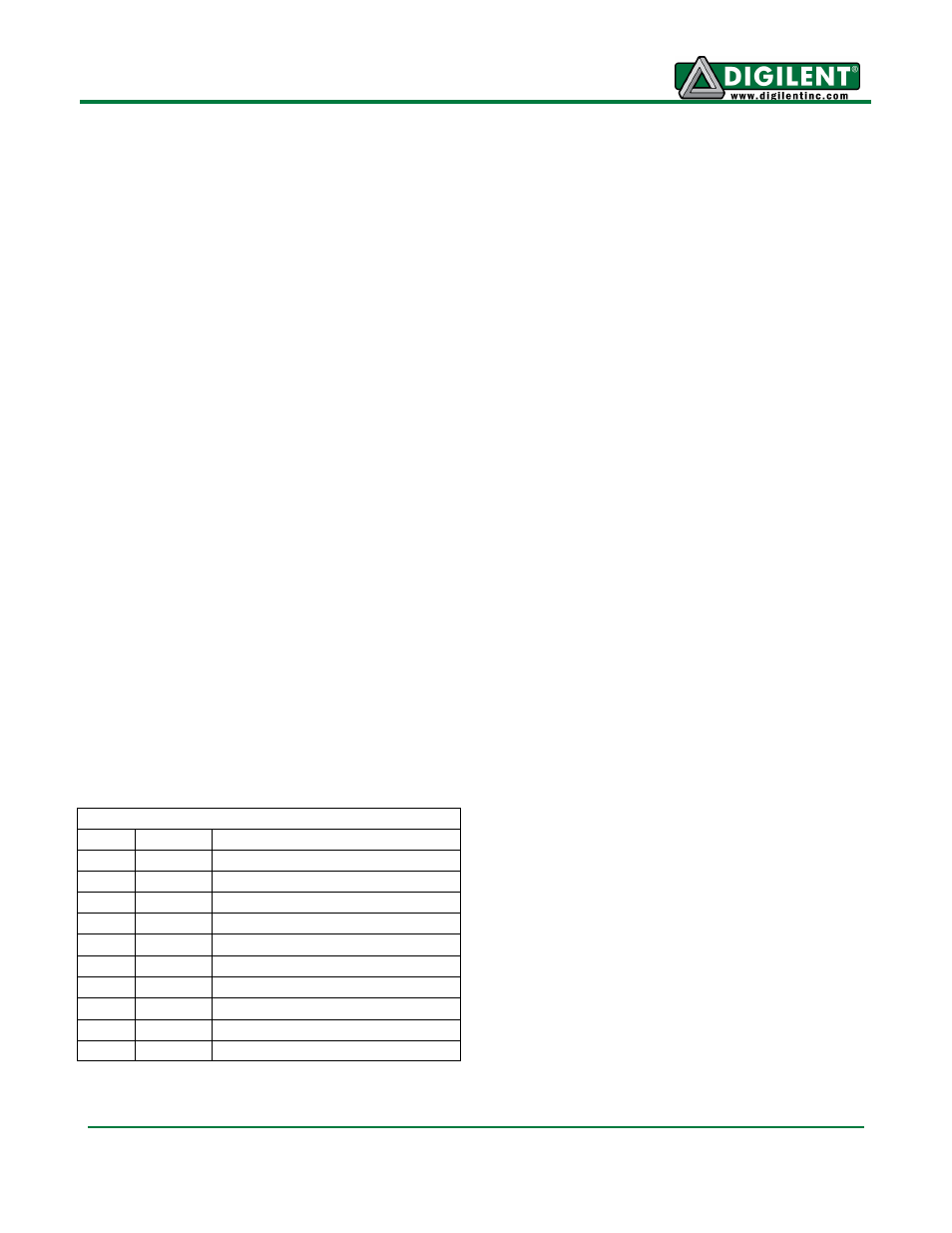
Connector J1
Pin
Signal
Description
1
CS
SPI Chip Select (Slave Select)
2
SDIN
SPI Data In (MOSI)
3
None
Unused Pin
4
SCLK
SPI Clock
7
D/C
Data/Command Control
8
RES
Power Reset
9
VBATC V
BAT
Battery Voltage Control
10
VDDC
V
DD
Logic Voltage Control
5, 11 GND
Power Supply Ground
6, 12 VCC
Power Supply
For more information on the OLED display
interface, see the UG-2832HSWEG04
datasheet available online or from Univisio.
The OLED display uses a compatible
command set from the SSD1306 device. For
more information, see the SSD1306 datasheet
available at www.solomon-systech.com.
Interface Connector Signal Description
Interface Connector Signal Description