Decoding rotations of the rotary shaft – Digilent 410-117P User Manual
Page 2
PmodXYZ Reference Manual
www.digilentinc.com
page 2 of 2
Copyright Digilent, Inc. All rights reserved. Other product and company names mentioned may be trademarks of their respective owners.
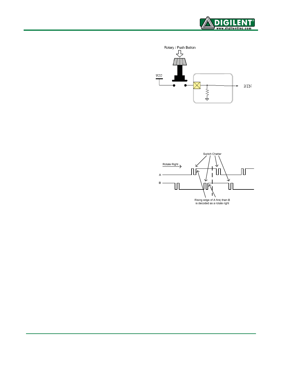
Pressing the rotary push-button shaft encoder
will drive the output pin BTN to VCC voltage or
a logic level 1. Otherwise BTN is driven to
GND voltage or a logic level 0.
Placing the slide switch into the up position on
the PmodENC module will drive the output
SWT to VCC voltage or a logic level 1. Placing
the slide switch in the down position will drive
SWT to GND voltage or a logic level 0.
Decoding Rotations of the Rotary
Shaft
Figure 4 shows a timing diagram of a rotate-
right on the rotary push-button shaft of the
PmodENC module. Note the logic noise shown
with opening and closing of the switches. A
rotate-left of the rotary push-button shaft is
similar to Figure 4. The only difference is that
output B will drop to logic level 0 first, followed
by output A.
Figure 3 Push-Button Circuitry
D
e
te
n
t
Figure 4 Timing of Outputs A and B