Digilent 410-214P-KIT User Manual
Page 2
PmodBT2™ Reference Manual
www.digilentinc.com
Copyright Digilent, Inc.
page 2 of 2
on jumper settings and functionality, refer to
the RN-42 user manual.
UART Interface
By default, the UART interface uses a baud
rate of 115.2 kbps, 8 data bits, no parity, and a
single stop bit. The startup baud rate may be
customized to predefined rates or set to a
specific user customized baud rate. Predefined
baud rates range from 1200 to 921k.
The reset pin (RST) on J1 is active low. If the
RST pin is toggled, the device will undergo a
hard reset. This hard reset performs similarly
to a power cycling of the device. The second
interface besides the standard UART signals is
the STATUS pin also on J1The STATUS pin
directly reflects the connection status of the
device. STATUS is driven high by the device
when connected and is driven low otherwise.
For more information on the devices UART
interface and RST and STATUS pins refer to
the RN-42 user manual on the Roving
Networks website.
Command Mode
In order to enter the command mode, the
PmodBT2 must receive “$$$” to which it will
respond “CMD”. When in command mode, the
module will respond to a large number of
commands allowing the user to customizing
the module for specific applications. In order
to exit command mode, send “---
minus signs in a row and where
for the carriage return character) to which the
device will respond “END”. Remote
configuration, or configuration over a Bluetooth
connection, is possible through the command
mode but has several restrictions. The
configure time, which defaults to 60 sec,
defines the time window in which the
PmodBT2 may be configured remotely.
Outside of this time, the PmodBT2 will not
respond to any remote commands. It is
important to note that any of the “set”
commands available for the PmodBT2 must be
followed by a power cycle to take effect in any
design.
The various modes of operation are accessed
by using the “SM,<5,4,3,2,1,0>” command
while in command mode. The PmodBT2 can
be put into one of six available modes of
operation. The modes in order, 0 to 5, are:
slave, master, trigger master, auto-connect,
auto-connect DTR, and auto-connect ANY. For
more detailed information on the different
modes of operation, refer to the RN-42 user
manual. For the full list of device commands,
how to use remote configuration, and more
detailed information on the different modes of
operation, see the RN-42 data.
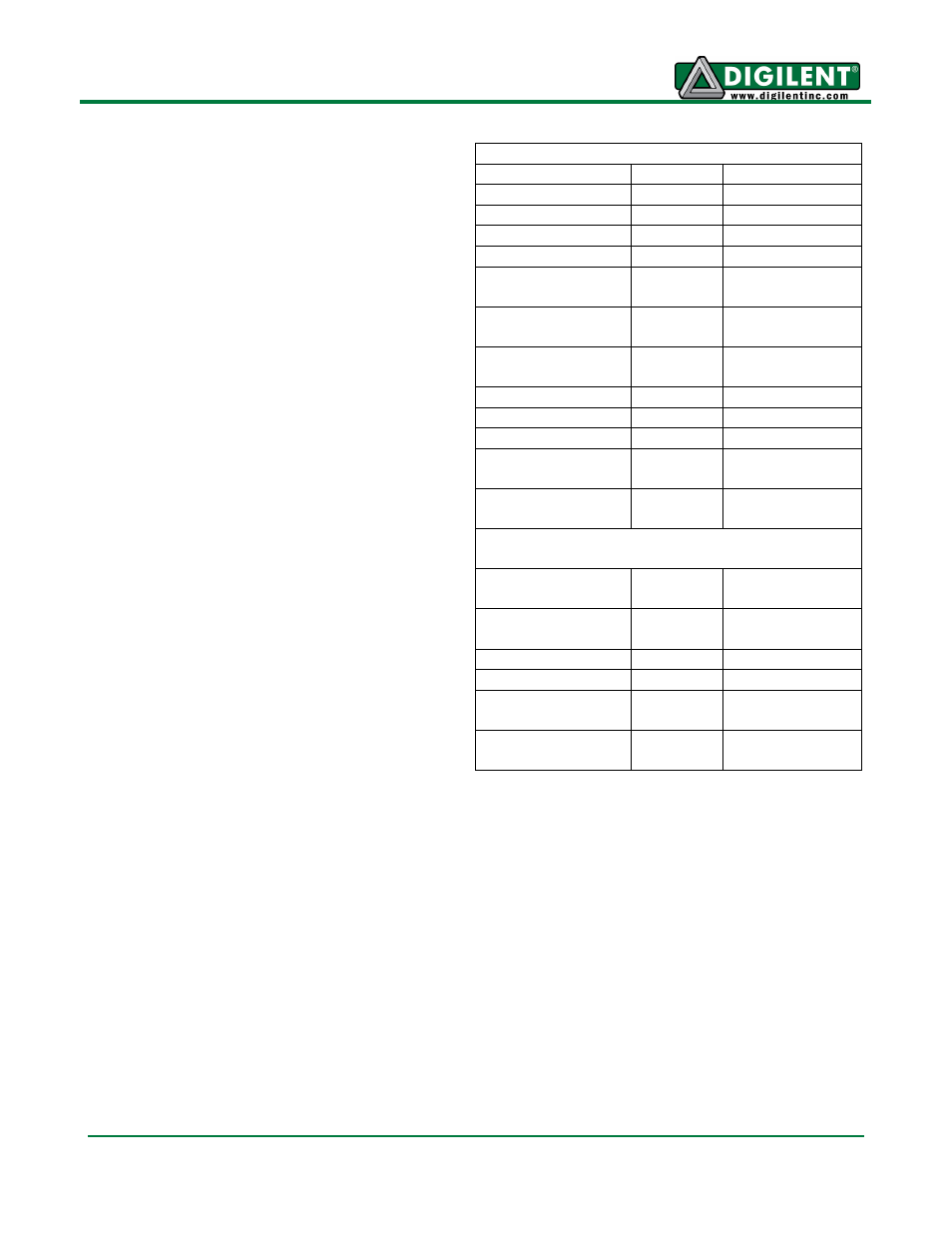
Connector J1 – UART Communications
Pin
Signal
Description
1
RTS
Ready to Send
2
RX
Receive
3
TX
Transmit
4
CTS
Clear to Send
5
GND
Power Supply
Ground
6
VCC
Power Supply
(3.3V)
7
STATUS
Connection
Status
8
~RST
Reset
9
NC
Not Connected
10
NC
Not Connected
11
GND
Power Supply
Ground
12
VCC
Power Supply
(3.3V)
Connector J2 – SPI Connector
(Firmware Update Only)
1
MISO
Master in/
Slave out
2
MOSI
Master out/
Slave in
3
SCK
Serial Clock
4
~CS
Chip Select
5
VCC
Power Supply
(3.3V)
6
GND
Power Supply
Ground
Table 2: Connector Descriptions