3physical dimensions, 4additional information – Digilent 410-286P User Manual
Page 2
PmodALS™ Reference Manual
Copyright Digilent, Inc. All rights reserved.
Other product and company names mentioned may be trademarks of their respective owners.
Page 2 of 2
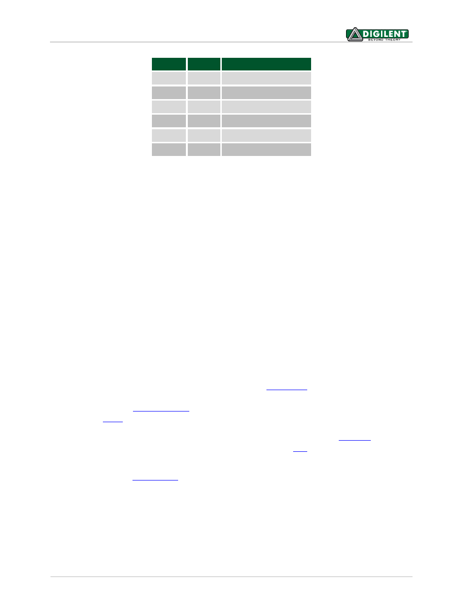
Table 1. Connector J1- Pin Descriptions as labeled on the Pmod.
The PmodALS reports to the host board when the ADC081S021 is placed in normal mode by bringing the CS pin
low, and delivers a single reading in 16 SCLK clock cycles. The PmodALS requires the frequency of the SCLK to be
between 1
MHz
and 4 MHz. The bits of information, placed on the falling edge of the SCLK and valid on the
subsequent rising edge of SCLK, consist of three leading zeroes, the eight bits of information with the MSB first,
and four trailing zeroes.
Any external power applied to the PmodALS must be within 2.7V and 5.25V; however, it is recommended that
Pmod is operated at 3.3V.
3
Physical Dimensions
The pins on the pin header are spaced 100 mil apart. The PCB is 0.8 inches long on the sides parallel to the pins on
the pin header and 0.8 inches long on the sides perpendicular to the pin header.
4
Additional Information
The schematics of the PmodALS are available for download from th
Additional information about
the ADC, including communication modes and specific timings of the chip, can be found by checking out its
datasheet
available from
Similarly, the datasheet for the ambient light sensor can be found on
the website fo
More specific information about how to use the PmodALS can be found by checking out our
Example
code demonstrating how to get information from the PmodALS can be found
If you have any questions or comments about the PmodALS, feel free to post them under the appropriate section
("Add-on Boards") of th
Pin
Signal
Description
1
CS
Chip Select
2
NC
Not Connected
3
SDO
Master-In-Slave-Out
4
SCK
Serial Clock
5
GND
Power Supply Ground
6
VCC
Power Supply