Analog inputs and v – Digilent 410-217P User Manual
Page 2
PmodAD2 Reference Manual
www.digilentinc.com
page 2 of 2
Copyright Digilent, Inc. All rights reserved. Other product and company names mentioned may be trademarks of their respective owners.
Analog Inputs and V
Ref
The PmodAD2 allows for up to four analog
inputs, VIN1 – VIN4. To use the input VIN4,
the jumper JP1 must be set to V4.
The configuration register has a REF_SEL bit
that, when enabled, allows a voltage other than
the supply voltage to be used as the reference.
If REF_SEL is enabled, and if JP1 is set to
REF, V
Ref
from the on-board voltage reference
generator is 2.048V. If JP1 is set to V4, V
Ref
is
the voltage at input VIN4.
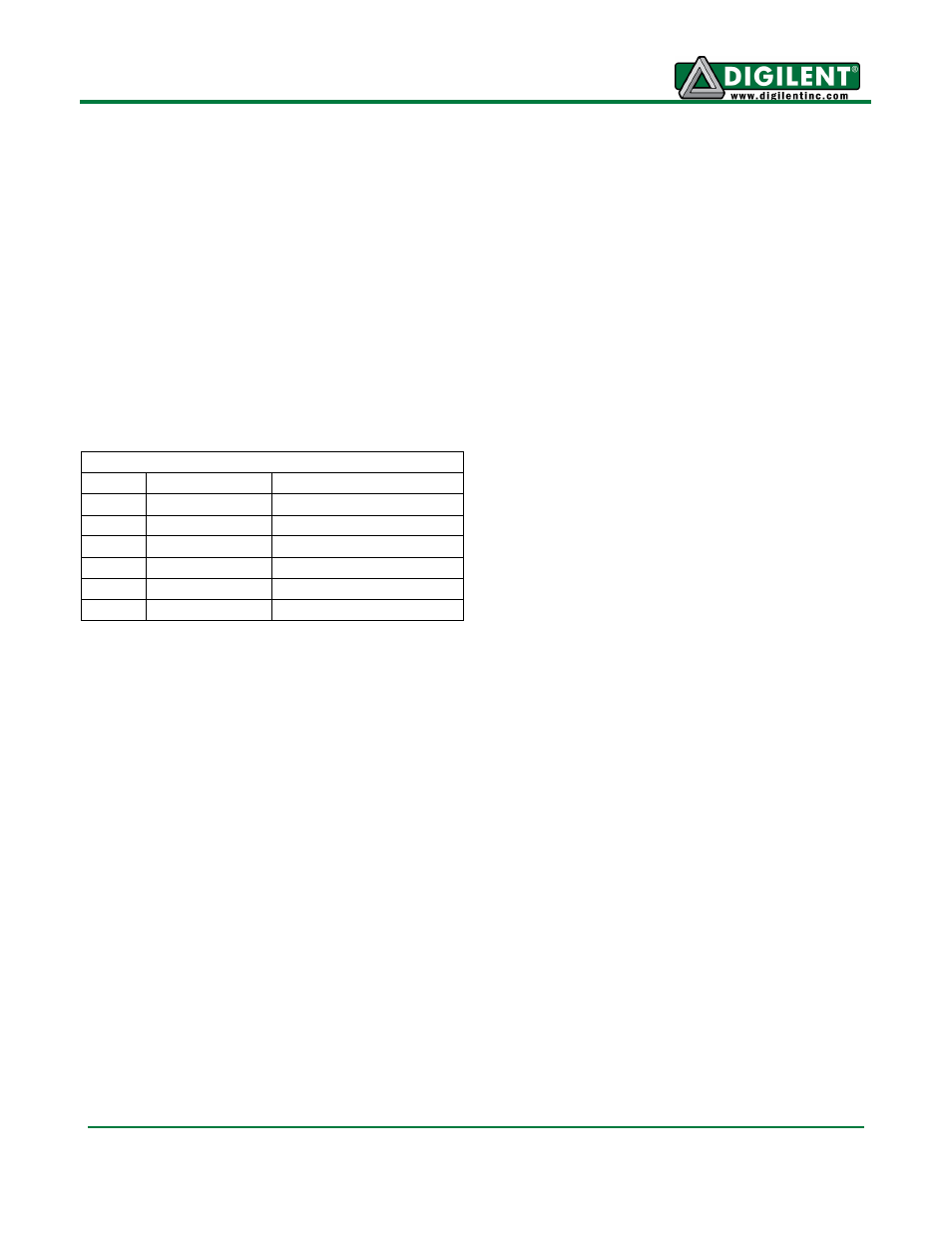
Connector J2 – Analog Input
Pin
Signal
Description
1
VIN1
Analog Input 1
2
VIN2
Analog Input 2
3
VIN3
Analog Input 3
4
VIN4
Analog Input 4
5
GND
Power Supply Ground
6
VCC
Power Supply (3.3V)
- 410-282P-KIT (4 pages)
- 410-279P-KIT (26 pages)
- 410-258P-KIT (16 pages)
- 410-138P-KIT (28 pages)
- 410-178P-KIT (22 pages)
- 410-292P-KIT (29 pages)
- 410-274P-KIT (29 pages)
- 410-182P-KIT (22 pages)
- 410-134P-KIT (17 pages)
- 410-183P-KIT (19 pages)
- 410-155P-KIT (12 pages)
- 6015-410-001P-KIT (26 pages)
- 410-087P-KIT (164 pages)
- 410-146P-KIT (4 pages)
- 6003-410-000P-KIT (138 pages)
- XUPV2P (23 pages)
- 410-047-C2P-KIT (3 pages)
- WaveForms (85 pages)
- 410-297P-KIT (25 pages)
- 410-295P-KIT (37 pages)
- 410-296P-KIT (23 pages)
- 410-209P-KIT REV.D (16 pages)
- 410-209P-KIT REV.C (17 pages)
- 410-254P-KIT (17 pages)
- 410-280P-KIT (9 pages)
- 410-202P-KIT (20 pages)
- 410-273P-KIT (24 pages)
- 410-269P-KIT (11 pages)
- 410-216P-KIT (15 pages)
- 410-231P-KIT (4 pages)
- 410-211P-KIT (10 pages)
- 410-262P-KIT (8 pages)
- 410-229P (7 pages)
- 410-242P-KIT (4 pages)
- 6021-210-000P-KIT (27 pages)
- 410-185P-KIT (21 pages)
- 6032-410-000P-BOARD (4 pages)
- 410-174P (17 pages)
- 410-145P (6 pages)
- 210-264P-BOARD (3 pages)
- 6003-210-012P (27 pages)
- 410-236P-BOARD (2 pages)
- 410-163P (1 page)
- 410-097P-KIT (2 pages)
- 410-255P-KIT (1 page)