Chipkit pgm hardware overview, Using the chipkit pgm – Digilent 410-242P-KIT User Manual
Page 2
chipKIT™ PGM Reference Manual
Copyright Digilent, Inc. All rights reserved.
Other product and company names mentioned may be trademarks of their respective owners.
Page 2 of 4
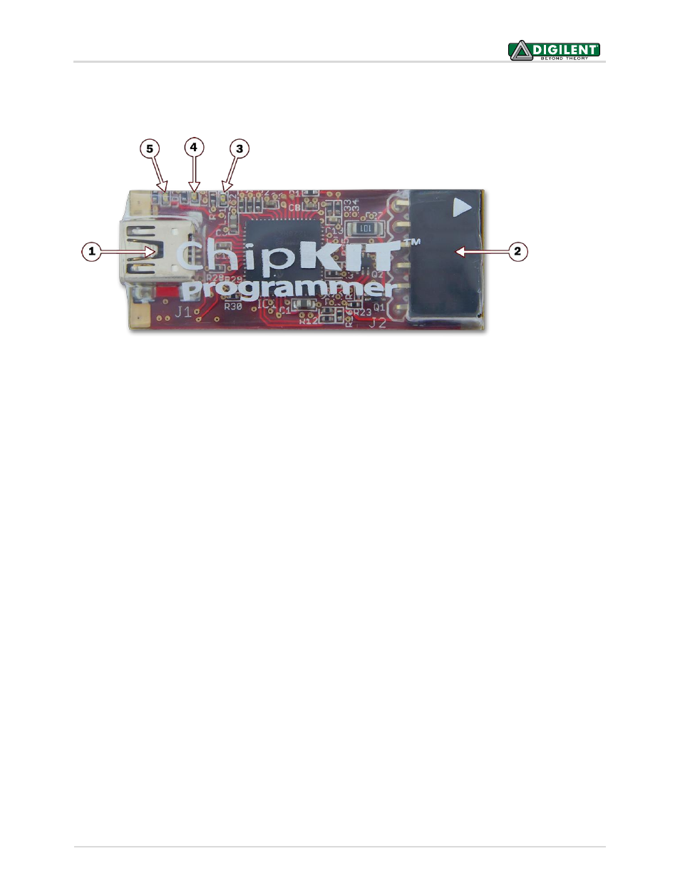
chipKIT PGM Hardware Overview
The chipKIT PGM has the following features:
1. USB Connector
This is a standard mini USB connector. Use the provided cable to connect the chipKIT PGM to an available
USB port on the PC workstation.
2. Programming Connector
Connect the chipKIT PGM to the target board using this connector. The white triangle marker indicates
the Pin 1 end of the connector.
3. Status LED
This LED indicates that the chipKIT PGM has connected to the target device and is ready for use.
4. Activity LED
This LED is an activity indicator. It blinks when the programmer/debugger software is communicating with
the target device.
5. Power LED
This LED illuminates when the chipKIT PGM is receiving power via the USB port from the host PC.
Using the chipKIT PGM
The chipKIT PGM uses a programmer/debugger circuit licensed from Microchip. Use of the chipKIT PGM requires a
supported version of either the MPLAB IDE or the MPLAB X IDE from Microchip. The licensed debugger is
supported in version 8.63 or later of the MPLAB IDE and all versions of the MPLAB X IDE.