7 pinout tables – Digilent 410-254P-KIT User Manual
Page 11
chipKIT™ uC32™ Board Reference Manual
Copyright Digilent, Inc. All rights reserved.
Other product and company names mentioned may be trademarks of their respective owners.
Page 11 of 17
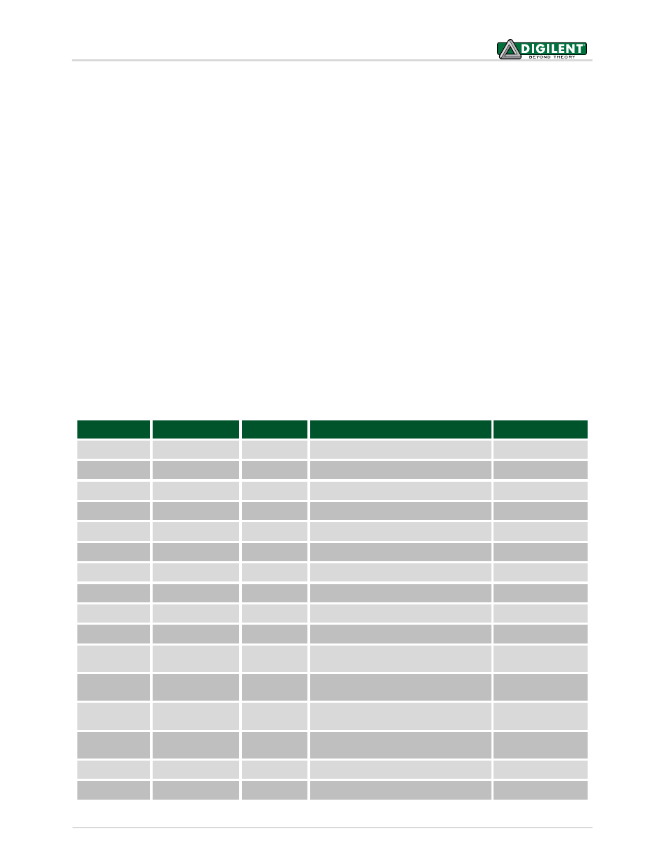
3.7 Pinout Tables
The following tables give the relationship between the chipKIT digital pin numbers, the connector pin numbers and
the microcontroller pin numbers. In the following tables, columns labeled chipKIT pin # refer to the digital pin
number. This is the value that is passed to the pinMode(), digitalRead(), digitalWrite(), and other functions to refer
to the pin.
For most pins, this pin number will agree with the pin number labeled on the board. For the pins whose function
can be switched using jumpers, the pin number labeled on the board is correct when the jumper is in the 'normal'
position.
For example, the normal position for JP4 is the RD4 position. The digital pin number for the microcontroller signal
RD4 is 10. With JP4 in the RD4 position, digital pin 10 is connected to the pin labeled 10 on the board. The
alternate position for JP4 is the RG9 position. The digital pin number for the microcontroller signal RG9 is 44. With
JP4 in the RG9 position, digital pin 44 is connected to the pin labeled 10 on the board, and digital pin 10 is not
connected.
The pin labeled 10 on the board is connected to connector J5 pin 5. This is shown as J5-05 in the following tables.
In the ‘Pinout Table by Shield Connector Pin’ table below, J5-05 is shown has being either chipKIT pin # 10 or 44.
J5-04 is connected to chipKIT pin # 10 when JP4 is in the RD4 position and is connected to chipKIT pin # 44 when in
the RG9 position.
3.7.1 Pinout Table by Logical Pin Number
chipKIT Pin #
Connector Pin #
PIC32 Pin #
PIC32 Signal
Notes
0
J6-01
34
U1RX/SDI1/RF2
1
J6-03
33
U1TX/SDO1/RF3
2
J6-05
42
IC1/RTCC/INT1/RD8
3
J6-07
46
OC1/RD0
4
J6-09
59
RF1
5
J6-11
49
OC2/RD1
6
J6-13
50
OC3/RD2
7
J6-15
43
IC2/U1CTS/INT2/RD9
8
J5-01
44
IC3/PMCS2/PMA15/INT3/RD10
9
J5-03
51
OC4/RD3
10
J5-05
52
PMWR/OC5/IC5/CN13/RD4
Selected by JP4,
also on J8-6
11
J5-07
6
SDO2/PMA3/CN10/RG8
Selected by JP5,
also on J8-1
12
J5-09
5
SDI2/PMA5/CN8/RG7
Selected by JP7,
also on J8-4
13
J5-11
4
SCK2/PMA5/CN8/RG6
Also on J8-3, User
LED LD4r
14/A0
J7-01
14
C2IN-/AN2/SS1/CN4/RB2
15/A1
J7-03
12
C1IN-/AN4/CN6/RB4