1chipkit uno32 hardware overview – Digilent 410-209P-KIT REV.D User Manual
Page 2
chipKIT™ Uno32™ Board Reference Manual
Copyright Digilent, Inc. All rights reserved.
Other product and company names mentioned may be trademarks of their respective owners.
Page 2 of 16
1
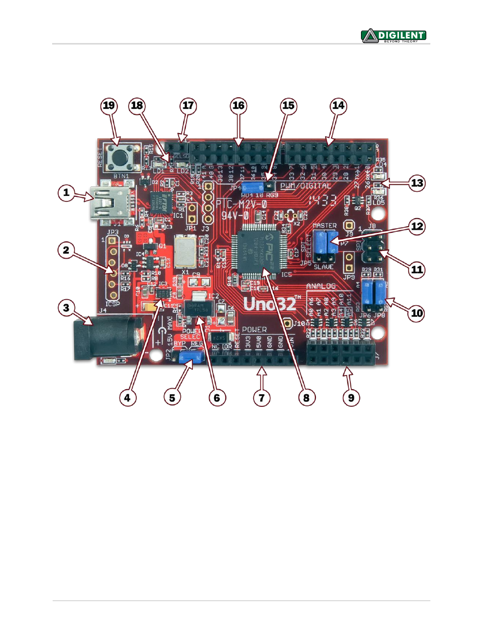
chipKIT Uno32 Hardware Overview
The Uno32 has the following hardware features:
Figure 1. The chipKIT Uno32 with hardware callouts.
1. USB Connector for USB Serial Converter
This connects to a USB port on the PC to provide the communications port for the MPIDE to talk to
the Uno32 board. This can also be used to power the Uno32 board when connected to the PC.
2. JP3 – Microchip Debug Tool Connector
This connector is used to connect Microchip programmer/debugger tools, such as the PICkit 3. This
allows the Uno32 board to be used as a traditional microcontroller development board using the
Microchip MPLAB
IDE.
3. J4 – External Power Connector
This is a 5.5mm x 2.1mm barrel connector used to power the Uno32 board from an external power
supply. It is wired with the center terminal as the positive supply voltage. The power supply voltage
must be in the range 7V to 15V.