Digilent 410-047-C2P-KIT User Manual
Page 2
Digilent C-Mod Reference Manual
Digilent, Inc.
www.digilentinc.com
page 2 of 3
Copyright Digilent, Inc. All rights reserved. Other product and company names mentioned may be trademarks of their respective owners.
When used in conjunction with the Ceres
board, C-Mods can be used to rapidly
implement CPLD based circuits, or to gain
exposure to Xilinx CAD tools and CPLD-
oriented design methods. The Ceres board
provides C-Mods with a power supply, a clock
source, input buttons and switches, and
various output LEDs. The Ceres/C-mod
combination makes an excellent platform for
use in teaching labs.
C-Mods are programmed with a sample design
during manufacturing. This design, available at
the Digilent website, can be used to verify C-
Mod/Ceres function. It also provides a simple
reference design example of a Xilinx project.
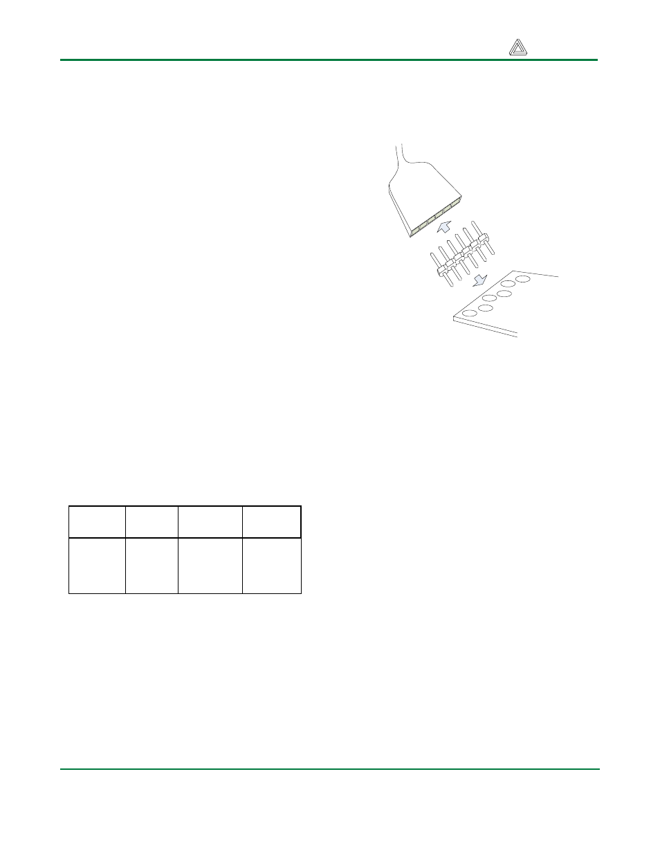
CPLD Configuration
C-Mod boards contain a JTAG port for CPLD
programming. The port consists of a pattern of
six offset holes that are not loaded with header
pins. To use this port, a row of six unattached
header pins can be inserted into the end of a
JTAG3 (or other) cable, and the other side of
the header can be inserted into the offset hole
patterns. Once the C-Mod board is connected
to the PC via the JTAG cable, the configuration
software will automatically detect the CPLD.
To configure the board from a computer using
the JTAG port, first ensure the C-Mod is
powered with a 3.3V supply (such as provided
by the Ceres board), and that the JTAG cable
is properly connected to the C-Mod and to the
computer. Start the configuration program
(e.g., the iMPACT programmer available in the
Xilinx WebPack tools), and the board will be
auto-detected. Device programming and other
JTAG operations are available in a pull-down
menu made visible by right clicking on the
device graphic in the programmer window.
JTAG3
Cable
6-pin
header
C-Mod
Figure 3. JTAG cable used with C-Mod
Power Supplies
C-Mod boards require a single 3.3V supply on
pin 20, and a single GND on pin 21. Current
consumption is dependant on CPLD family,
CPLD configuration, and external circuits. In
most cases, current will be far less than
100mA, but the Xilinx data sheets for the
particular CPLD should be referenced for more
information.
CPLDs
C-Mod boards are available with CoolRunner-
2, CoolRunner (XPLA), and XC95 CPLDs. All
available CPLD I/O signals are routed to the
DIP connector, and the JTAG signals are
routed to a programming connector. CPLD
pinouts are provided in tables 2 and 3 below.
Please see the data sheets for the CPLDs
available at the Xilinx web site for more
information.
JTAG
Signal
XC2C64
pin
XC9572XL
pin
XCR3064
pin
TCK 11 11
26
TDI 9 9
1
TDO 24 24
32
TMS 10 10
7
Table 1. CPLD JTAG Pins