D.A.S. Audio LX-218RA User Manual
Page 10
4
EN
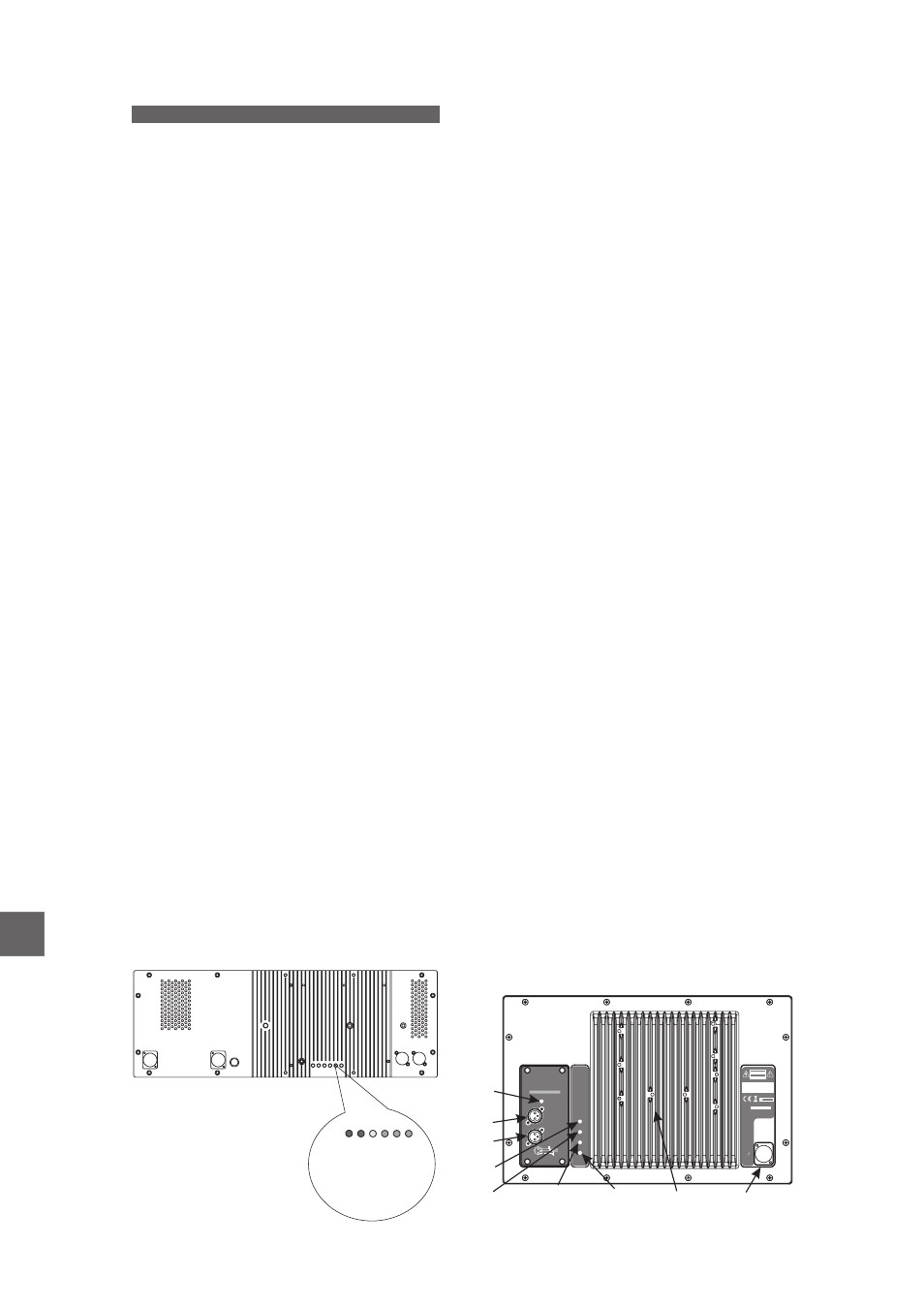
AMPLIFIER DESCRIPTION
aero 38A
LX-218A & LX-218RA
Three way self powered system.
Nominal amplifier power: LF:1000W, MF:500W,
HF:500W, (RMS, class D).
A) LIMIT:
Amplifier limiter indicator lights. When lit, the
level of the signal source should be reduced.
Signal presence indicator at the amplifier’s
inputs.
C) ON:
Indicator light for amplifier channels.
E) FUSE.
B) SIGNAL:
D) PROTECTION:
Indicates that the amplifier is under protection
mode because damage risk due to short circuit or
extreme working temperature.
F1) AC INPUT:
F2) AC OUTPUT:
6
(at 230V)
G)
INPUT:
1=GND (ground)
2=(+) Non inverted input
3=(-) Inverted input
H) LOOP THRU:
With PowerCon NAC 3 FCA
connector. Only when the connector is inserted
and rotated (clicked) into place will the AC turn on.
The connector can be used as a switch, rotating
the connector to or from the locked position will
turn the unit on or off, respectively. Mute the signal
feeding the INPUT
before turning the unit on or
off.
With (white) PowerCon NAC
3 FCB connector. This is used as an AC loop thru
so that up to
boxes
can be power from
a single AC line.
Balanced
signal
XLR.
Pin
assignments as follows :
Used for paralleling several
units, which will share the same input. The output
can also be used to provide signal for an outboard
power amplifier.
F2-PowerCon NAC 3DFCB
HF
(RED)
G-Input XLR
E-Fuse
H-Output XLR
F1-PowerCon NAC 3FCA
SIGNAL
(GREEN)
MF
(RED)
LF
(RED)
ON
(GREEN
PROTECTION
(YELLOW
)
D
A A
A
B
ZOOM
H
G
F1
E
F2
C
Low frequency mono-amplified system.
Nominal amplifier power: 2400W (RMS, class
D).
A) INPUT CLIP:
Red LED indicates and excessive input signal,
saturation of the DSP and excessive increases in
distortion.
B) LOOP THRU :
XLR-type
output
signal
connector
for
connecting several units together and sending
them all the same signal.
C) INPUT :
XLR-type input signal connector, which just like
the
LOOP
THRU
connector,
is
a
balanced
connector with the following pins:
1=GND (Ground).
2=(+) Non invertided input.
3=(-) Invertided input.
D) CLIP :
Red LED indicates amplifier saturation, in other
words, when it reaches Clip.
E) PROTECTION :
Yellow
LED
indicates
that
the
protection
system has been activated. If the problem that
activated the protection is resolved, the amplifier
will restart. The problems that can activate the
protection system are:
-Mains power out of operating range
-Overheating.
-Overload or short-circuit.
-DC voltage present at the loudspeaker output.
F) SIGNAL :
Green LED indicates signal.
G) POWER :
Green LED indicates ON.
H) Heatsink.
Although the heatsink does not reach high
temperatures (during normal use), the heatsink
should not be covered or obstructed in any way
and it should not be touched.
I) AC INPUT :
Neutrik model PowerCon 'NCA3' connector for
connection
to
the
mains
supply.
This
only
connects when it is turned and locked and is
equipped with a securing tab.
CAUTION
RISK OF ELECTRIC SHOCK
DO NOT OPEN
ATTENTION
DANGER D’ELECTROCUTION
NE PAS OUVRIR
N1918
D.A.S. AUDIO S.A. (Valencia) SPAIN
MADE IN SPAIN
100V-230V
1200W
MA
X.
50Hz/60Hz
AC
IN
PU
T
S.N.
INPUT
LOOP THRU
INPUT CLIP
Line Array Series
POWER
SIGNAL
PROTECTION
CLIP
GND
COLD
HOT
2
3
1
DSP INPUT BOARD
B
A
F
D
H
C
G
E
I
Manual del Usuario
/ aero 38A & LX-218RA / User’s Manual