Building additional loopback plugs, Hardware specifications, Notices – Comtrol RocketPort Serial Hub Si 2-Port User Manual
Page 5: Radio frequency interference (rfi) (fcc 15.105), Labeling requirements (fcc 15.19), Specification, Agency notices
Building Additional Loopback Plugs
5 of 6
Building Additional Loopback Plugs
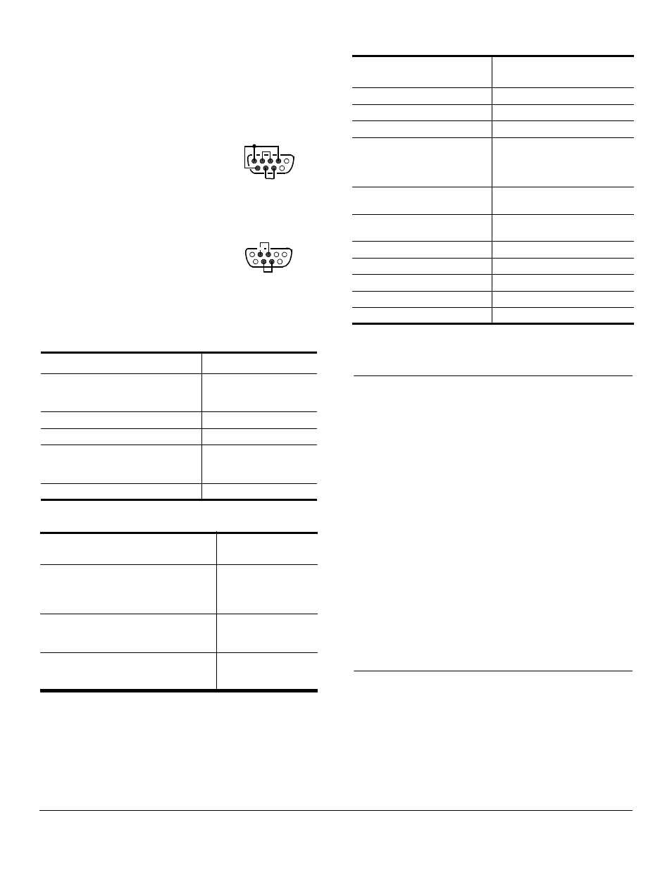
Loopback connectors are DB9 female serial port plugs,
with pins wired together as shown, that are used in
conjunction with the diagnostic software to test serial
ports. The RocketPort Serial Hub Si is shipped with a
a single loopback plug (RS-232/422).
This information can help you build additional plugs or
replace a missing loopback.
Wire the following pins together
for an RS-232 loopback plug:
•
Pins 1 to 4 to 6
•
Pins 2 to 3
•
Pins 7 to 8
Note: The RS-232 loopback plug
also works for RS-422.
Wire the following pins together
for an RS-422 loopback plug:
•
Pins 2 to 3
•
Pins 7 to 8
Hardware Specifications
This table illustrates environmental conditions.
The following table lists electromagnetic compliance
certifications.
The following table illustrates hardware specifications.
Notices
Radio Frequency Interference (RFI) (FCC
15.105)
This equipment has been tested and found to comply
with the limits for Class A digital devices pursuant to
Part 15 of the FCC Rules.
This equipment generates, uses, and can radiate radio
frequency energy, and if not installed and used in
accordance with the instruction manual, may cause
harmful interference to radio communications.
However, there is no guarantee that interference will
not occur in a particular installation. If this equipment
does cause harmful interference to radio or television
reception, which can be determined by turning the
equipment off and on, the user is encouraged to try and
correct the interference by one or more of the following
measures:
•
Reorient or relocate the receiving antenna.
•
Increase the separation between the equipment
and the receiver.
•
Connect the equipment into an outlet on a circuit
different from that to which the receiver is
connected.
•
Consult the dealer or an experienced radio/TV
technician for help.
Labeling Requirements (FCC 15.19)
This equipment complies with part 15 of FCC rules.
Operation is subject to the following two conditions:
•
This device may not cause harmful interference,
and
•
This device must accept any interference received,
including interference that may cause undesired
operation.
Environmental Conditions
Value
Air temperature:
System on
System off
0 to 40
o
C
-20 to 85
o
C
Altitude
0 to 10,000 feet
Heat output:
BTU/Hr
Humidity (non-condensing):
System on
System off
8% to 80%
20% to 80%
Mean Time between Failures
38.8 years
Electromagnetic
Compliances
Status
Emission:
Canadian EMC requirements
CISPR-22/EN55022
Class A
FCC Part 15 Class A
Yes
Immunity:
EN50082
(801-2
ESD
, 801-3 RF,
and 801-4
FT)
Yes
Safety:
EN60950
UL Listed
Yes
Pin 1
Pin 5
Pin 6
Pin 9
RS-232 Only
(Back View)
Pin 1
Pin 5
Pin 6
Pin 9
RS-422 Only
(Back View)
Topic
Hardware
Specifications
Baud rate (maximum)
115.2 Kbps
Current consumption:
20 mA (at 120 VAC)
Dimensions
6.1” x 4.28” x 1.18”
Driver Control:
Data bits
Parity
Stop bits
7 or 8
Odd, Even, None
1 or 2
Ethernet host interface
10/100Base-T (10/100
Mbps - RJ45)
Hubs per server
Dependent on OS, see the
software documentation
Line frequency
50 - 60 Hz
Line voltage
100 - 240 VAC
Number of ports
2
Power consumption:
2.4 W
Weight
9.5 oz