Connecting devices, Building an ethernet crossover cable, Db9 connector pinouts – Comtrol RocketPort Serial Hub Si 2-Port User Manual
Page 4: Building null-modem cables, Building straight-through cables, Build cables or loopback plug
Connecting Devices
4 of 6
Connecting Devices
Use the following discussion to connect asynchronous
devices to the RocketPort Serial Hub Si ports.
Note: Make sure that you have configured the ports
using the driver for the correct communications
mode before connecting any devices. The default
mode is RS-232. There is a remote possibility
that connecting a peripheral configured for the
wrong mode could damage the peripheral.
1.
Connect your devices to Ports 1 or 2 for each
RocketPort Serial Hub Si using the appropriate
cable or you can build your own cables using the
discussions.
Note: Use the hardware manufacturer’s installation
documentation if you need help with connector
pinouts or cabling for the peripheral device.
2.
Install or reconfigure the driver using the
Software
Installation
documentation or the driver readme
file.
Building an Ethernet Crossover Cable
If you are connecting from the
10/100Base-T connector on the
RocketPort Serial Hub Si
directly to the NIC card in the
server, you need a crossover
cable. Use the following
information to build a cable, if
necessary.
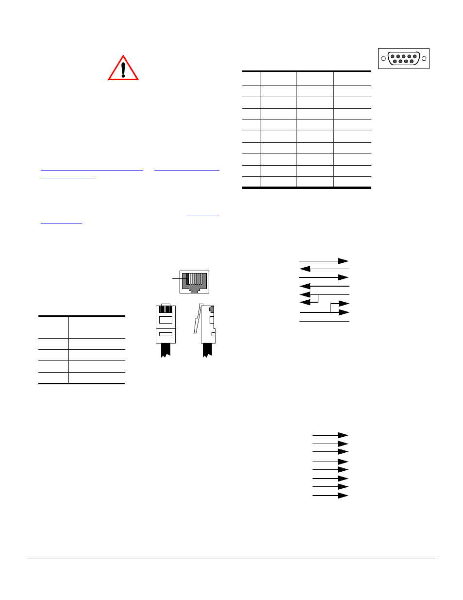
DB9 Connector Pinouts
Use the following pinout
information for the DB9 serial port
connectors on the RocketPort Serial
Hub Si.
Building Null-Modem Cables
Use the following figure if you need to build a null-
modem cable. A null-modem cable is required for
connecting DTE devices.
Note: You may want to purchase or build a straight-
through cable and purchase a null-modem
adapter.
Building Straight-Through Cables
Use the following figure if you need to build a straight-
through cable. Straight-through cables are used to
connect DCE devices.
Pin
Connects to
Pin
1
3
2
6
3
1
6
2
Caution
Pin 1
Pin 6
Receptacle
Pin 1
Pin
RS-232
RS-422
RS-485
1
CD
Not used Not used
2
RxD
RxD-
Not used
3
TxD
TxD-
TRX-
4
DTR
Not used Not used
5
GND
Not used Not used
6
DSR
Not used Not used
7
RTS
TxD+
TRX+
8
CTS
RxD+
Not used
9
Not used Not used Not used
Pin 1
Pin 5
Pin 6
Pin 9
DB9 Male
RPSH
-Si
Connect
or
TxD
RxD
RTS
CTS
DSR
GND
DCD
DTR
Signal
RxD
TxD
CTS
RTS
DTR
GND
DCD
DSR
Signal
DB9
2
3
8
7
4
5
1
6
Pins
DB25
3
2
4
7
8
6
Pins
Remote and
RPSH
-Si
DB9
3
2
7
8
6
5
1
4
Pins
20
5
Pin 9 is not connected.
Fe
m
a
le
Connect
ors
Null-Modem Cables
RPS
H
-Si
Connect
or
DB9
1
2
3
4
5
8
6
7
Pins
DCD
RxD
TxD or TRX-
DTR
GND
CTS
DSR
RTS or TRX+
Signal
DB9
1
2
3
4
5
8
6
7
Pins
DCD
RxD
TxD or TRX-
DTR
GND
CTS
DSR
RTS or TRX+
Signal
RPSH
-Si
C
o
nnect
or
Pin 9 is not connected.
Fe
m
a
le
Fe
m
a
le
Straight-through Cable