5sr tihis'l, Connections, Awarning – Kenwood KRC-601 User Manual
Page 45: English
Attention! The text in this document has been recognized automatically. To view the original document, you can use the "Original mode".
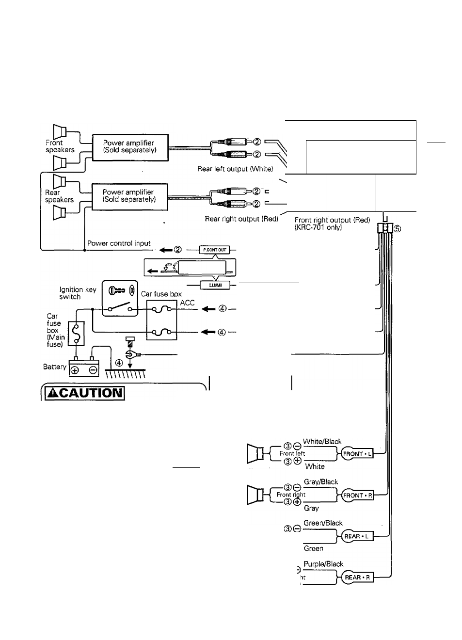
Connections
NOTE
To connect the Disc-changer,
consult your Disc-changer
manual.
-V Output
Kenwood Disc-changer
(optional)
* Circled numbers indicate the
procedures described in the
Installation Procedure,
ger connection cable (Supplied
the Kenwood disc-changer)
FM/AM antenna input
--------------
t-fT-
■ !
Front left output
(White)
(KRC-70T only)
_____
i
________
_______ 1
Disc-
changer
control
Fuse
gi.
3
CO
(—i*
q
T
<—h
o'
3
Power/Fu!t automatic power antenna
i- control cable CBIueA/Vhite)
Automatic ilJumination/Dimmer control,
cable (Orange/Whlte) {To carjight control
switch) (KRC-701' oniy)
Ignition cable {Red)
Battery cable (Yellow)
Ground cable (Black) © (To car chassis)
When two speakers are connected to the
system, be sure to connect both of them to the
front output or rear output. In other words, do
not connect the positive connector of the left
speaker to the front output and the negative
connector to the rear output,
White/Black
Front
left
speaker
ÜH
2
® e -
Front left
Front 1^
right
speaker
White
Gray/Black
j^-(^NT*
l
|
Green/Black
Green
Purple/Black
Purple
AWARNING
Front right
speaker
Rear right
speaker
To prevent fire when the Ignition cable (Red) or
battery cable (Yellow) is short-circuited by coming
into contact with the vehicle chassis (ground), only
connect the power supply after making the fuse box
connections,
Front left
speaker
5sr tIHIS'l»
Purple
Wiring
harness
(Accessory)
English
45