Installation instructions (cont’d), Water piping, Xa warning – Kenmore THE ECONOMIZER 153.33298 User Manual
Page 13: A warning, T&p valve and pipe insulation, Installation instructions
Attention! The text in this document has been recognized automatically. To view the original document, you can use the "Original mode".
Installation Instructions (cont’d)
Water Piping
’XA WARNING
HOTTER WATER CAN SCALD; Water heaters are intended to
produce hot water. Water heated to a temperature which will
satisfy clothes wishing, dish washing, and other siuiitizing needs
can scald and permanently injure you upon contact. Some peo
ple are more likely to be permanently injured by hot water than
others. These include the elderly, children, the infirm, or physi
cal ly/mentally handicapped. If anyone using hot water In your
home fits into one of these groups or if there is a local code or
state law requiring a certain temperature water at the hot water
tap, then you must take special precautions. In addition to using
the lowest possible temperature setting that satisfies your hot
water needs, a means such as a mixing valve, should be used at
the hot water taps used by these people or at the water heater.
Mixing valves are available at plumbing supply or hardware
stores. Follow manufacturers instructions for installation of the
valves. Before changing the factory setting on the thermostat,
read the “Temperature Regulation” section in this manual.
HOT WATER A
OUTLET T
TEMPERED
WATER
OUTLET
COLD WATER
INLET
«MIXING
VALVE
FROM HOT
WATER
OUTLET
ON WATER
HEATER
TO COLD WATER
INLET ON WATER
HEATER
A WARNING
This water heater shall not be connected to any heating sys
tems or component{s) now or previously used with a non
potable water heating appliance.
A WARNING
Toxic chemicals such as used for treatment of boilers or
non-potable water heating appliances shall never be intro
duced into a potable water heating system.
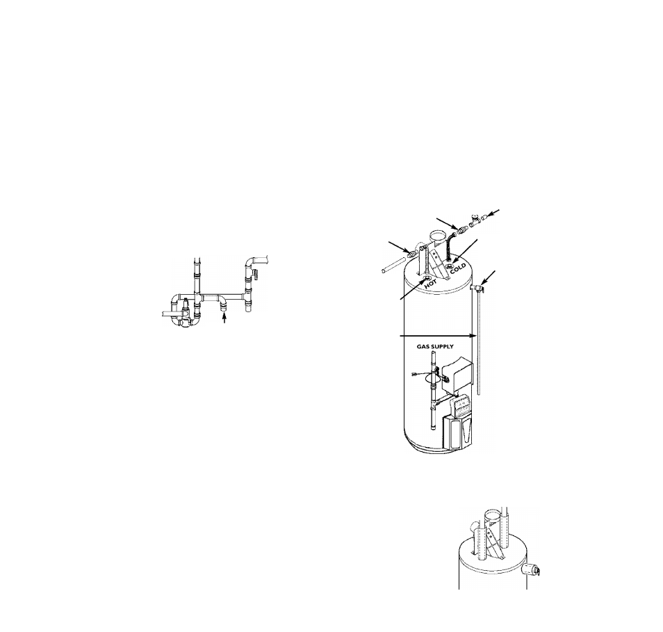
1. Look at the top cover oi the water heater. The hot water outlet is marked hot.
Put two or three turns of teflon tape around the threaded end of the threaded-
to-sweat couplirrg and around both ends of the
V
threaded nipple. Using flexi
ble connectors, connect the hot water pipe to the hot water outlet on the water
heater.
2. Look at the top cover of the water heater. The cold water inlet is marked cold.
Put two or three turns of teflon tape around the threaded end of the threaded-
to-sweat couplirrg and around both ends of the
V
threaded nipple. Using flexi
ble connectors, connect the cold water pipe to the cold water inlet of the water
heater.
NOTE: This water heater is insulated to minimize heat loss from the tank.
Further reduction in heat loss can be accomplished by insulating the hot
water lines from the water heater.
INSTALLATION COMPLETED
THREADED TO
SWEAT COUPLING
THREADED TO
SWEAT COUPLING
HOT OUTLET
TO HOUSE
3/r THREADED
NIPPLE
COLD INLET
SHUTOFF WATERLINE
VALVE
V4" THREADED
NIPPLE
DISCHARGE
PIPE
(Do not cap or
ping)
PROVIDE A 6"
AIR GAP
BETWEEN THE
END OF THE
DISCHARGE
PIPE AND DRAIN
TEMPERATURE-
PRESSURE
RELIEF VALVE
If a water heater is installed in a closed water supply system; such as one having a
back-flow preventer, check valve, water meter with a check valve, etc... in the cold
water supply; means shall be provided to control thermal exparrsion. Contact the
local utility or local Sears Service Center on how to control this situation.
NOTE: To protect against untimely corrosion of hot and cold water fittings,
it is strongly recommended that dielectric unions or couplings be installed on
this water heater when connected to copper pipe.
The illustration shows the attachment of the water piping to the water heater. The
water heater is equipped with 7i inch water connections.
NOTE: If using copper tubing, solder tubing to an adapter before attaching
the adapter to the cold water inlet connection. Do not solder the cold water
supply line diRctiy to the cold water inlet or it will harm the dip tube.
T&P Valve and Pipe Insulation
Remove insulation for T&P Valve and pipe connections from carton.
Fit pipe insulation over the incoming cold
water line and the hot water line. Make
sure that the insulation is ^inst the top
cover ot the heater.
Fit T&P Valve insulation over valve. Make
sure that the insulation does not interfere
with the lever of the T&P valve.
Secure all insulation using tape.
13