Carl Goldberg GBGA1053 User Manual
Page 22
.
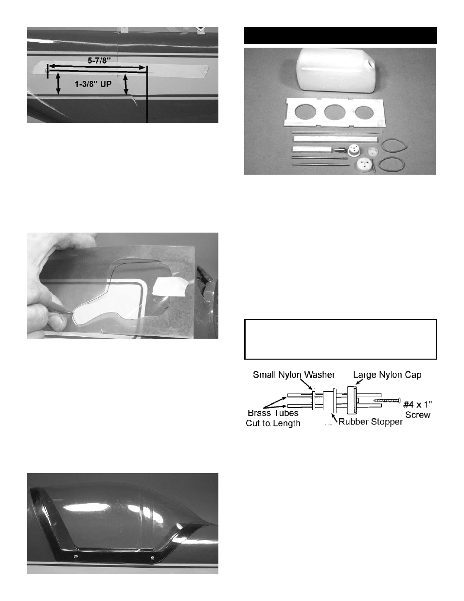
Place a piece of masking tape down the cen-
ter of the wide yellow trim stripe.
Measuring up 1-3/8” from the bottom of the
yellow stripe, make two marks and draw a
line on the tape, parallel to the yellow stripe.
Make a third mark on the tape, even with the
back of the landing gear. From this point,
measure forward 5-7/8”.
Drill a 1/16” hole at this location for the top
cowl screw.
10.
With the fuselage on its left side, trace the
cutout for the engine onto the cowl.
Remove the cowl and, with a moto tool, slow-
ly remove the fiberglass INSIDE the cutout
outline. Work slowly and carefully, until the
cowl matches the clear plastic piece.
Remember, if the fiberglass is damaged dur-
ing this process, it can be repaired only with
epoxy glue.
NOTE:You may wish to make a cutout in the front of
the cowl, at the point where the engine prop washer
sticks out, that is large enough to allow the engine to
vibrate without touching the cowl.
Fuel Tank Installation
1.
Collect the following items:
(1) Fuel tank
(1) Fuel tank platform
(2) #30 rubber bands
(2) Brass tube
(1) Large nylon cap
(1) Small nylon washer
(1) Rubber stopper
(1) #4 x 1” screw
(1) Fuel tank klunk
(1) 6” length of white fuel tubing
(1) 1/4 x 3/8 x 2-1/2” fuel tank stop
(1) 1/4 x 3/8 x 5-1/2” fuel tank support
CAUTION! The white neprene stopper and the fuel
tubing provided with this kit are FOR GLOW FUEL
ONLY; DO NOT USE THESE PARTS FOR GASO-
LINE.
2.
Insert both brass tubes through the wide end
of the rubber stopper. Leave 1/2” extending
out the front of the tank.
Place the small nylon washer on both tubes,
as shown, making sure that one of the tubes
extends 1” past the washer. This tube will be
for the klunk pickup.
Cut tube as necessary.
22