Carl Goldberg GBGA1053 User Manual
Page 21
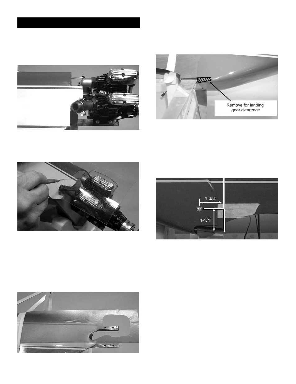
2.
Check to see if any part of the engine muffler
or exhaust header will interfere with the fuse-
lage. If necessary to create clearance,
remove a portion or the entire tab that
extends beyond the firewall.
3.
Place the piece of clear plastic over the top
of the engine. The end of the plastic should
extend just past the cylinder head.
4.
Mark where the engine contacts the plastic.
Remove the plastic and, using the moto tool,
cut out the engine area until the plastic fits
over the top of the motor and lies flat on the
fuse side. Then, tape the edges of the plas-
tic to one side of the fuselage.
Using the moto tool, cut away the bottom of
the cowl at the point where it hits the land-
ing gear. Take off small amounts at a time
and keep measuring the cowl until it will slide
back to a point that is 1/16” behind the
engine drive washer.
NOTE: If using the engine pictured in these instruc-
tions, the measurement from the firewall to
the front of the cowl will be 5-3/8”.
7.
Securely tape the cowl to the fuselage, so
that it will not move. Once taped, measure
the cowl again to make certain its position
has not shifted.
8.
Place a piece of masking tape on the side of
the fuselage just above the landing gear and
long enough so that it extends 3” onto the
cowl and behind the landing gear.
Placing the plane on its side, measure 1-1/4
above the landing gear and make a mark on
the tape.
From the mark, on a plane parallel to the yel-
low striping, measure 1-3/8” and make a
second mark.
Drill a 1/16” hole on the second mark for the
lower cowl screw.
Turn the aircraft over and repeat the above
steps, drilling a bottom hole on the other
side.
6.
Slide the cowl under the plastic.
CAUTION! WHEN CUTTING THE COWL, ALWAYS
WEAR PROTECTIVE EYE GEAR AND A LONG-
SLEEVE SHIRT. CHANGE CLOTHES AND WASH
AFTER CUTTING.
Cowl Installation
1. Collect the following items:
(1) Fiberglass cowl
(4) #4 x 3/8 sheet metal screws
(4) #4 washers
(1) 4 x 12” clear plastic
5.
Lift up the untaped side of the plastic and
remove the engine.
21