Ex-treme 330 3-d arf – Carl Goldberg GBGA1070 User Manual
Page 7
EX-TREME 330 3-D ARF
15.
Trim 3 arms from a 4 arm servo wheel. Center
your aileron servos with your radio, then install
the trimmed servo arms on the aileron servos.
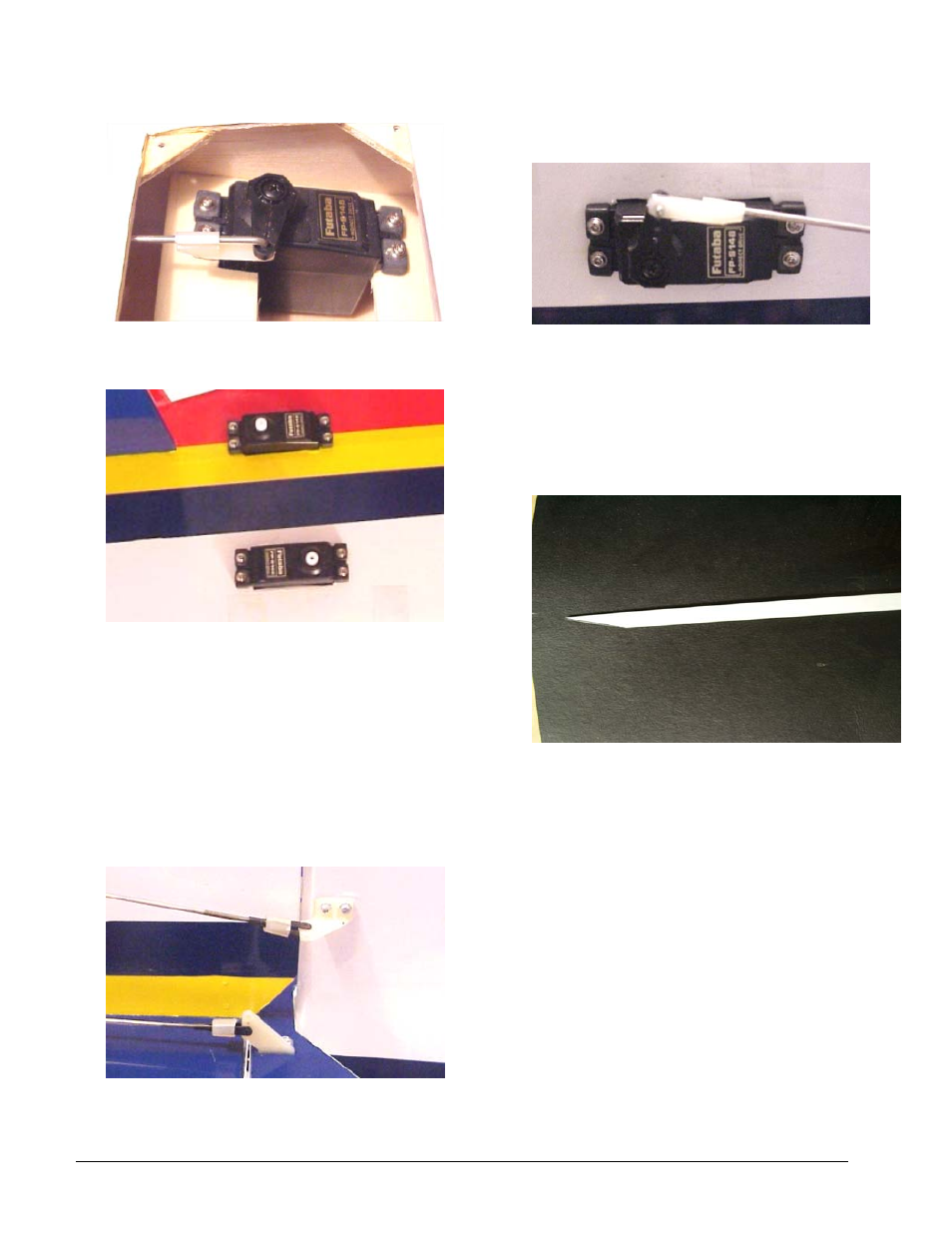
16.
Locate the servo positions in the rear of the fuse
and remove the covering with a sharp hobby
blade.
17.
Install your rudder and elevator servos in the
openings, keeping the servo tops on the left side
of the fuse. Center the servos with your radio.
18.
Trim two more 4 arm servo wheels and install on
the servos, then locate the control horn positions
as was done for the ailerons, for the elevator and
rudder, trying to keep the rod positions 90
degrees to the control surface.
19.
Install the control horns with the small machine
screws, then install clevis and rod on each horn.
20.
Position the rods across the servo horns, mark,
make an “L” bend, then trim as before. Secure
the rod on the servo wheel with an “L” keeper.
21. Use the included wire tube , two brackets, and 4- 2mm
x10mm screws to hold the wires down the length of
the fuse
22.
Cut the tube at an 11degree angle on one end.
23.
24.
Lay the angle cut on the tube on the bottom of
the wing next to the fuselage with the back end of
the tube just in front of the bottom servo. Mark
the position for the hole and cut a notch in the
bottom of the wing next to the fuselage 3/16"
wide and 1/2" long for the rudder and elevator
servo leads
to exit the wing into the
© 2002 Carl Goldberg Products, Inc.
Page - 7