Ex-treme 330 3-d arf – Carl Goldberg GBGA1070 User Manual
Page 6
EX-TREME 330 3-D ARF
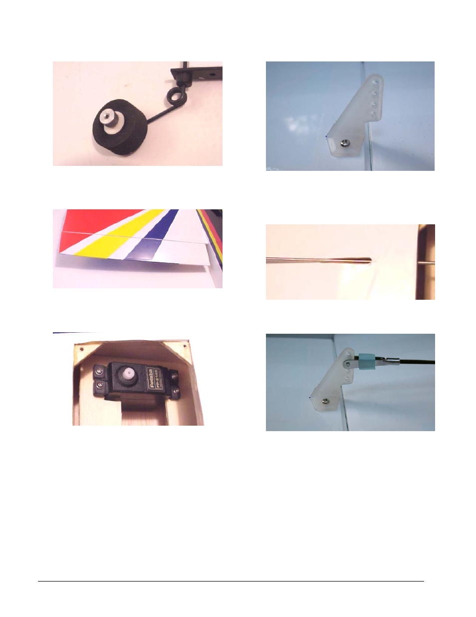
9.
Install the tail wheel on the bracket using a small
inner diameter wheel collar and set screw on each
side of the wheel. Use thread lock on each set
screw.
10.
Trial fit, then install an aileron on each side of
the wing with 4 CA hinges and pink zap. Make
sure the wing tip and aileron tip are aligned
before you glue.
11.
Install two aileron servos and one throttle servo
in the wing. You may need to open the servo
trays to accept the size of your servos. Use a
hobby blade or razor saw to open the servo trays.
The aileron servos should be located to the
outside of the servo trays from the fuse, the
throttle servo needs to be close to the fuse.
12.
Position the aileron control rods off the servos,
toward the ailerons, keeping the rods 90 degrees
to the ailerons. Mark the position of the aileron
control horns, then install them with the 2mm x
20mm machine screws and backing plates.
13.
Trim a hole using a sharp hobby blade, just
behind the radio hatch on each side of the wing,
aligned with the servo, for the aileron control rod.
14.
Use a clevis on the threaded end of the control
rod and install one on each control horn. Lay the
rod across the servo arm, then make an “L” bend
at each intersection. Trim each rod to ¼” from
the bend, install in the horn, and secure with an
“L” keeper. Place a small piece of fuel tubing on
each clevis to lock in place.
© 2002 Carl Goldberg Products, Inc.
Page - 6