Stab assembly – Carl Goldberg GBGA1040 User Manual
Page 4
3.
Trial fit the stab in place on the fuselage. Place a
piece of making tape across the fuselage in front of
were the stab mounts.
Measure across the fuselage and mark the center.
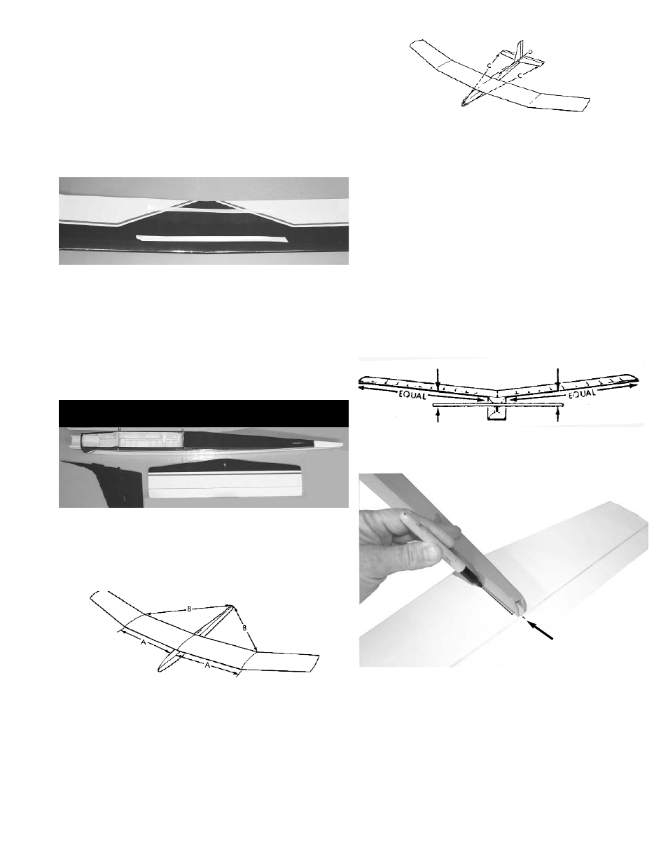
4.
Place two strips of masking tape along the edge of
the stab, next to the both outer stab tips and above
the hinge line.
Using a T-square or triangle, draw a line from the
front center point of the stab to the rear hinge line.
Measure 9-1/2” out ("B") from each side of the cen-
terline and make a mark on the masking tape.
5.
Measure from the marks on the stab to the polyhe-
dral breaks on the wing adjust as necessary to line
up with wing.
Mark the stab and fuse with matching line-up points.
4
Spread the epoxy in the joiner pockets and in the
dowel hole and spread a thin layer of epoxy along
one side of the entire center joint area.
Immediately proceed to the next step.
4.
Working rapidly, so that the epoxy does not set
before you are finished, slide the wing joiner into
one wing pocket.
Then slide the wing halves together until they are
touching. Make sure the rear dowel slides into the
dowel hole.
5.
With masking tape, tape the wing halves together at
the trailing edge and close to the leading edge, as
shown. This will help keep the wing from twisting.
Place additional tape at several locations across the
center seam of the wing, so that the halves stay
firmly together while the epoxy sets.
Allow the epoxy to dry thoroughly.
Note: Both outer wing tips should be about
6-3/8” off the table top.
Stab Assembly
1.
Mount the wing on the fuselage using the rubber
bands provided
Measure carefully from the fuse sides out to the
polyhedral breaks (arrows ‘A’) to be sure that the
wing is centered.
2.
Now measure from the polyhedral to the back end
of the fuselage(arrow ‘B’) to make sure wing is
square to the fuselage.
Mark the wing and the fuselage with matching line-
up points.
1.
Collect the following parts:
(1) Fuselage
(1) Stabilizer
(1) Fin
(2) Control Horn
(4) Screws
7.
Make sure the stab is level (parallel) with the wing
and insert paper strip shims, if necessary.
Elevator Mark
8.
When satisfied with the alignment of the stab, tem-
porarily tape securely in place.
Turn over the plane and mark the area on the bot-
tom of the stab where it rests on the fuse.